TL:dr:: New tax law lets everyone deduct $300 in donations. This will really help i3 and other small charities. Donate if you can.
In 2018, the Tax Cut and Jobs Act was enacted. This made things harder for an awful lot of small charities, like i3. This was because the changes included doubling the standard deduction, which generally had a positive effect on most people’s tax burdens, but significantly reduced the likelihood of people of itemizing deductions. And since there aren’t any tax benefits for donating to charities when you don’t itemize deductions, donations to small charities dropped by quite a bit.
However, as a response to the Covid-19 emergency, the CARES Act was enacted. Part of this law was a minor adjustment to the tax code that allows up to $300 in donations to a valid 501(c)3 to be deductible, even if you don’t itemize deductions. IRS has information about it here. Like other so-called “above the line” deductions, you’ll be able to report this deduction directly on the face of your 1040. But this deduction is only good for 2020, so to get the deduction, the donation has to happen by midnight on 31 December.
Especially in these challenging times, small charities like i3 are really struggling and your donation could really help. So if you can afford it, during this holiday season, you can look forward to a small benefit for yourself.
Thank you for all of your support and Happy Holidays from all of us at i3Detroit. (And if you want to donate to us, you can do so here.)
Do you want to paint a 3D printed baby alien with an optional Santa hat? Of course you do. Then sign up and come on down to i3Detroit’s Classroom next Monday evening 12/30/2019 7pm – 9pm. We have all the paints, brushes, palettes, and miniatures for a $5 material fee. Maximum 8 participants. Thanks to Christopher Frieze for sculpting “The Child” model. Comment below with links to any files ideas for the next Miniature 3D Print and Paint a long in 2020!
Mini figurine paint-a-long: "baby alien" with Santa hat. Watch for additional paint-a-long workshops in the near future!
https://www.i3detroit.org/wp-content/uploads/2014/03/Logo_large_png8-300x98.png00switlikmhttps://www.i3detroit.org/wp-content/uploads/2014/03/Logo_large_png8-300x98.pngswitlikm2019-12-27 12:29:072019-12-27 12:30:09Miniature Paint a Long: The Child
My dad has been an avid small-boat sailor for absolutely forever, with his dad taking him out for the first time in 1965 when he was 8 years old. He took to it like a duck to water (pun). Grandpa had purchased a 14′ daysailer made (at the time) by MFG, of a class called the Pintail (see, pun). Dad bought it off him in 1975. Dad started taking me out on his boat when I was about 6 months old, and I have deeply enjoyed it all my life as well.
As the story goes, he and the rest of the Pintails used to have to select race times and even lakes from a lottery, so large and myriad were the small-boat fleets in northern Oakland County in the late 1960s and 1970s. When Dad came back to SE MI a few decades later (after running about the world for work, then settling in Milwaukee and raising me and my brother), he discovered that the fleets were gone. He teamed up with the owner of Avon Sailboats to start a mixed-fleet casual racing fleet on Stony Creek Metropark, CreekFleet.
His dream the last decade has been to get into one-design racing, where all boats on a given starting line are of the same class. This means that positions crossing the finish line are the actual race results; no handicaps, no calculations in the committee room. He has been buying and selling as many Pintails as he can get his hands on, trying to bolster the fleet, since he and I are effective caretakers of the National Pintail Class Association. Trouble is, despite bringing 12 boats into the area, we can rarely attract more than a handful to race at a time.
This winter, he was approached by someone who wanted to get rid of a slightly larger boat called a Wayfarer (I bet you were wondering where I was going with this). The Wayfarer fleets in the US Midwest and all the way up into Toronto are enormously active, so this boat might finally be the chance to do one-design regattas like the Bayview One Design series or the Clark Lake Fall Regatta.
But of course there are downsides to cheap boats. This particular boat, sail #2413, had not only seen better days but also had never been raced. While the Wayfarer is a racing sloop, #2413 had spent the years since her hull was laid in 1970 as a cruising family boat, and she bore none of the fittings or controls that a racing boat of her class typically bears. While there are many further stories to tell about Wayfarer #2413, newly dubbed “THX 1138: Stay Calm.” (because my dad is a giant nerd and gave it all to me too), the particular one I am trying to get to here is that of the “magic box”.
Unlike a lot of other small racing sloops, the Wayfarer class does not tension the rig by tightening the forestay. Instead, the jib hoist is used to apply as much as 300-400 pounds of tension (sue me, I was raised in the US) to the rig. The issue is, #2413 being a cruiser, only had a bare halyard and the grunt of the crew (me) to put as much tension on it as she could (not much), hampered further by the routing of the free end of the halyard out of the bottom of the mast, through a turning block, and thus pulled upwards to tension relying then on the crew’s (me) muscles (very minimal especially after a year of HRT). Most racing Wayfarers either use a 40:1 block and tackle set to tension the halyard after the sail was hoist, or a worm-driven friction winch contraption affectionately dubbed a “magic box”.
Since dad was uncertain whether he would keep #2413, he was reluctant to put the kind of money into her just yet that either of those venerable solutions would run him. In addition, as a not-very-svelte, not-very-graceful crewmember, I disliked the solutions because they are bulky and liable to give me even more things to run into during fast racing maneuvers. Enter my replacement (finally!).
Design
I figured that a winning design needed to meet the following:
Be cheap, preferably under $100 to replicate
Be reasonably easy to make with common machine shop tools (though to be honest a CNC mill would have been helpful)
Be compact, preferably protruding less than an inch into the cockpit from under the deck
Mount along the side of the tabernacle, to catch the halyard as is dropped out of the bottom of the mast
Be operable underway without power tools
As such, I ended up basing the design around an ACME leadscrew. Compact, inexpensive, and powerful, and driven easily by a socket and ratchet onboard (though a power drill on shore makes much quicker work of it). The system is self-contained, putting minimal force onto the old wood of the tabernacle, and protrudes barely enough for a socket to clear the drive nut. A basic metal lathe and manual mill are the only machines needed to make the custom parts, though of course CNC variants of either would turn out more consistent parts more quickly.
Custom Parts
There were a handful of custom parts that had to be produced, either from raw stock or as modifications to purchased components:
Turned from the leadscrew stock, one end is threaded for the 1/4-20 acorn nut, then cross-drilled for a roll pin to retain it. Both ends are turned to be a turning fit in the bushings.
I turned the bushing seats first, then further reduced a section on one end to the threading diameter for a 1/4-20 die. Then I hand-threaded it with a die; I hate cutting small threads on the Acer.
One exciting and unexpected incident was that the length of leadscrew was slightly longer than the Acer can turn in a stable fashion, and so suddenly the section in the spindle bore threw itself to one side and violently shook until I could stop the lathe. As a result, my leadscrew is slightly bowed. I fixed this by wadding it up with shop towels until it was a snug fit, and that kept things true for the rest of the cutting work.
Bushing Blocks
I squared up the piece of 6061 that would become both blocks and the car, then indicated it in clamping in a square fixture and the vice with the long axis vertical. Then I drilled and reamed for the leadscrew clearance hole all the way through the piece — pair drilling in the finest form!
After this, I parted off the rough thicknesses for the blocks on the bandsaw, then took them to final dimensions with a shell mill. I picked up the bore with an indicator, and counterbored one face on each block for the flange of the bushing.
I drilled and tapped the two 6-32 holes on the bottom of each block, then stamped a “T” and a “B” into each, to aid in reassembly (top and bottom block, stamps face the same way). Then I shaped the top curve on the belt sander, smoothed the cutter marks on a Scotchbrite wheel, then polished with a medium grit polish and buffer.
A light press on the Arbor press set the bushings in place at depth, and the leadscrew ran smoothly in each block. I did end up coming in and reaming the bushings back to 0.2510″, because installed on the frame, the leadscrew’s gentle curve jammed the system at certain points.
Car
Once parted from the bushing blocks above, much the same treatment was done: cut to final dimensions on the shell mill, drilled and tapped the 12-24 holes for the V cleat. However, I also carefully slotted the side to encompass the bronze nut firmly and centered on the reamed bore.
To dress and break the edges, I used a carbide 1/8″ round over router bit on the highest speed the old Bridgeport spindle can reach (about 2500rpm). Cut like a dream with a little Tap Magic. Once softened, the same Scotchbrite and polish steps were performed.
Frame
The frame was simple: On each of the two faces in turn, zero the DRO on the corner as a datum, then center drill and drill each hole per the face’s hole chart, countersinking as needed. Two tapped holes did get the better of me, but I was using cheap carbon steel taps from Lowe’s so this was more or less expected.
Bench Testing
I had to test, of course!
Tensioning Test
Relax and Break Test
Deviations
Had to replace the 6-32 fasteners for the block attachment fitting with 1/4-20 points because I broke off the 6-32 tap in those holes.
Had to ream the bushings because the leadscrew is slightly bent due to the incident above.
Installation
Mark the top hole, ensuring that the upper end of the frame is secure against the bottom of the deck, there is clearance for the 7/16″ socket to drive the acorn nut, and the lower end is flush with the aft side of the tabernacle. Drill a hole through the tabernacle large enough for the shaft of the tee nut. Install the tee nut and clamp down to set it using a strong clamp. Install a 6-32 1.25″ screw and mark the remainder of the five mounting holes. Remove the screw and drill those, then reinstall all five screws into their respective tee nuts.
Our connecting link had an opening too small to fit over our lacing eye, so we just leave the RF280 captive by a stop knot on the halyard. To rig, once the mast is up, simply drop the block’s loop into the connecting link and secure, then hoist the jib normally. Once taut, set the halyard into the V cleat and tension using the screw.
Use
Testing
The day before Clark Lake, we fitted the system to the tabernacle and put tension to the rig for the first time. 125 pounds, easy, and hardly any backpressure on the ratchet handle. The forestay went slack as it was supposed to, the rig being held by the halyard.
The system works well, though 12tpi means lots and lots of turning. A power drill or screwdriver is recommended for shore work. The system stays nicely out of the way during even heavy air sailing (I have many bruises, but none of them from the tensioning system).
All CAD files, in both original Autodesk Inventor 2019 (*.ipt) and IGES interchange (*.igs) formats, as well as 2D prints for the custom parts in both DXF and PDF, can be found on this project’s Thingiverse page. This allows for downloading, editing, and commenting for changes.
VR Meetup: Rec Room Thursday 8/29/2019 7pm-10pm!
We are rebuilding i3Detroit inside of Rec Room in the ^i3Detroit Custom Room. Show up at i3 or attend remotely via PC, PS4, or VR. We will have i3Detroit’s Oculus Quest and a few other VR headsets running at i3Detroit.
https://recroom.com
https://rec.net/event/22400
If you are new to building stuff in Rec Room check out some of the basic How To Rec Room videos on Youtube.
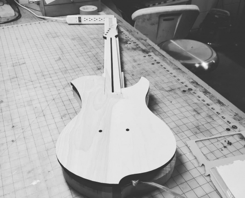
From the first glance at the Tusano Trading Company’s wares, it makes immediate sense that Thomas’s humanities thesis at LTU was on “The value of craft … trying to find the place where making and thinking meet”. He came to i3 after outgrowing the woodshop on campus, and over two years, has developed a wide variety of works and a small business to encompass them.
But among all the furniture and other wooden works, it’s the guitars that really stand out as his passion. Embracing the modern CNC and laser-cutting capabilities at i3, he’s both working on new designs, and spearheading the creation of a library of open-source designs, “a drawing-back of the curtain on the mechanics of the modern guitar”.
https://www.i3detroit.org/wp-content/uploads/2014/03/Logo_large_png8-300x98.png00Nate Bezansonhttps://www.i3detroit.org/wp-content/uploads/2014/03/Logo_large_png8-300x98.pngNate Bezanson2019-07-22 16:13:502019-07-22 16:15:01Guitars, Furniture, and more: the Tusano Trading Company at Maker Faire Detroit


 VR Meetup: Rec Room Thursday 8/29/2019 7pm-10pm!