Ham Radio Mobile Install
Preamble
I am a simple girl. I like little cars. I like sporty cars. I like putting my foot down and zoomy happening. I also happen to like mobile radio operation. This poses a number of packaging challenges; for some reason, no one is building small, sporty cars with ham radio operation in mind.
About a month ago, I totaled my car. RIP Matilda; she died valiantly protecting us, and rides on to Valhalla. Matilda was a 204 Mazda3 s Grand Touring with the tech package, and around 136,000 miles. (HATCH LYFE)
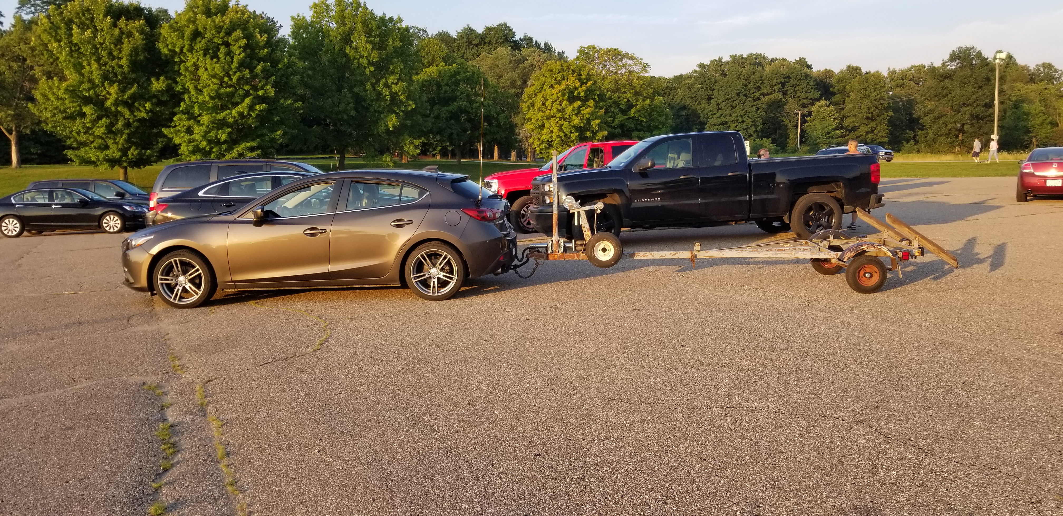
Matilda, with bonus appearance of the trailer for my boat, Aly Kat. Note the HV-7A antenna on a K400S mount on the hatch.
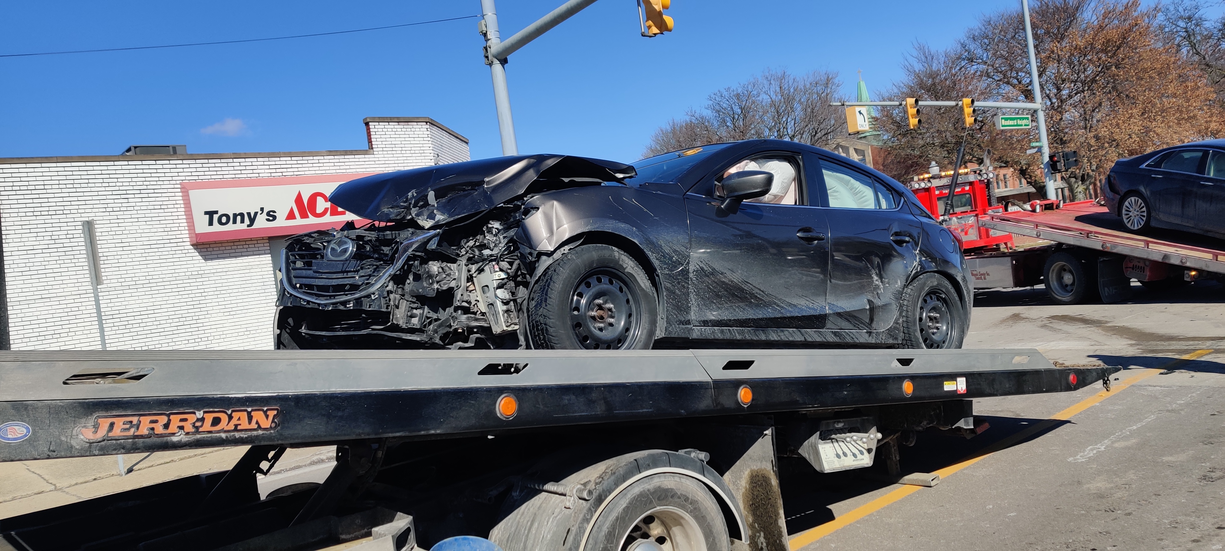
Matilda, on her final journey to Valhalla. Note the ATAS-120A on the same lip mount.
So I figured that, with my new car Minerva (a 2019 Mazda3 Sport hatch, with around 1200 miles), I would take the opportunity to ditch the mildly-inconvenient Diamond K400S hatch mount I was using for my Diamond HV-7A antenna (and recently my Yaesu ATAS-120A antenna), and put two brand-new Breedlove 195 SO239 ball mounts onto the car.
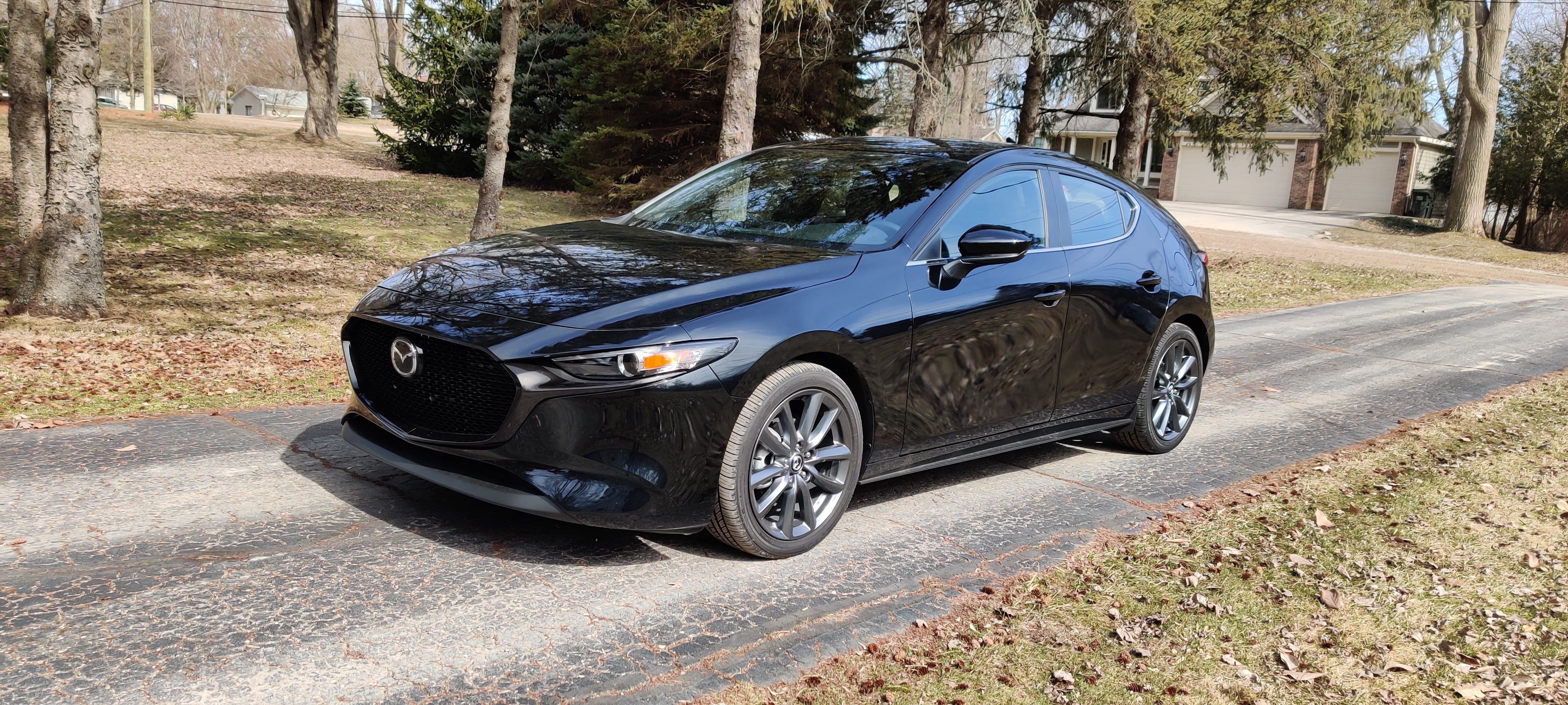
New car, Minerva. Note there are no antennae yet.
But of course I also like my cars to be clean and functional inside, so I needed to spend a lot more time than I did on Matilda with the radio install now that I have two mobile units. Also, I wanted big plates on the mounts so I did not can-opener the body steel…
Power
First and foremost, I needed a lot of power. The Yaesu FT-8900R daily rig draws up to 15A full-bore, and the Yaesu FT-857D all-band/all-modes rig draws 22A full-bore. In addition, I want to run my trailer light harness (LED lights on the car means I need a transistor box and a battery feed to run the trailer), and since Mazda for some unknown reason has something against accessory ports (seriously there is one gorramed port in the whole car), a 20A drop on PowerPole in the trunk is a good idea.
I had wired Matilda with some specialty AWG8 that was scrap from work, but I was not able to salvage much of that from her and plus I am under quarantine. However, I had a little left on the spool of AWG6 THHN from running a 50A 240VAC run to my garage. Score!
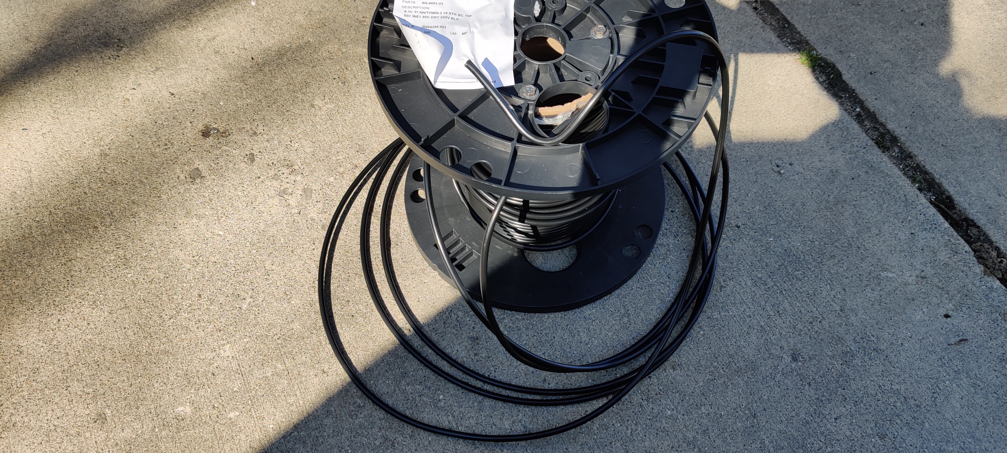
The remains of a spool of AWG6 THHN from Anixter, I used for a 50A 240VAC run to my garage.
I bought some lugs and a crimper from Amazon to suit my sub-panel and the distribution block on the battery (Mazda is super helpful here!). The distribution block has several M6 studs with built-in high-current fuses. The panel and the wire are rated for around 80A in this use case, and conveniently there is an 80A fuse spare.
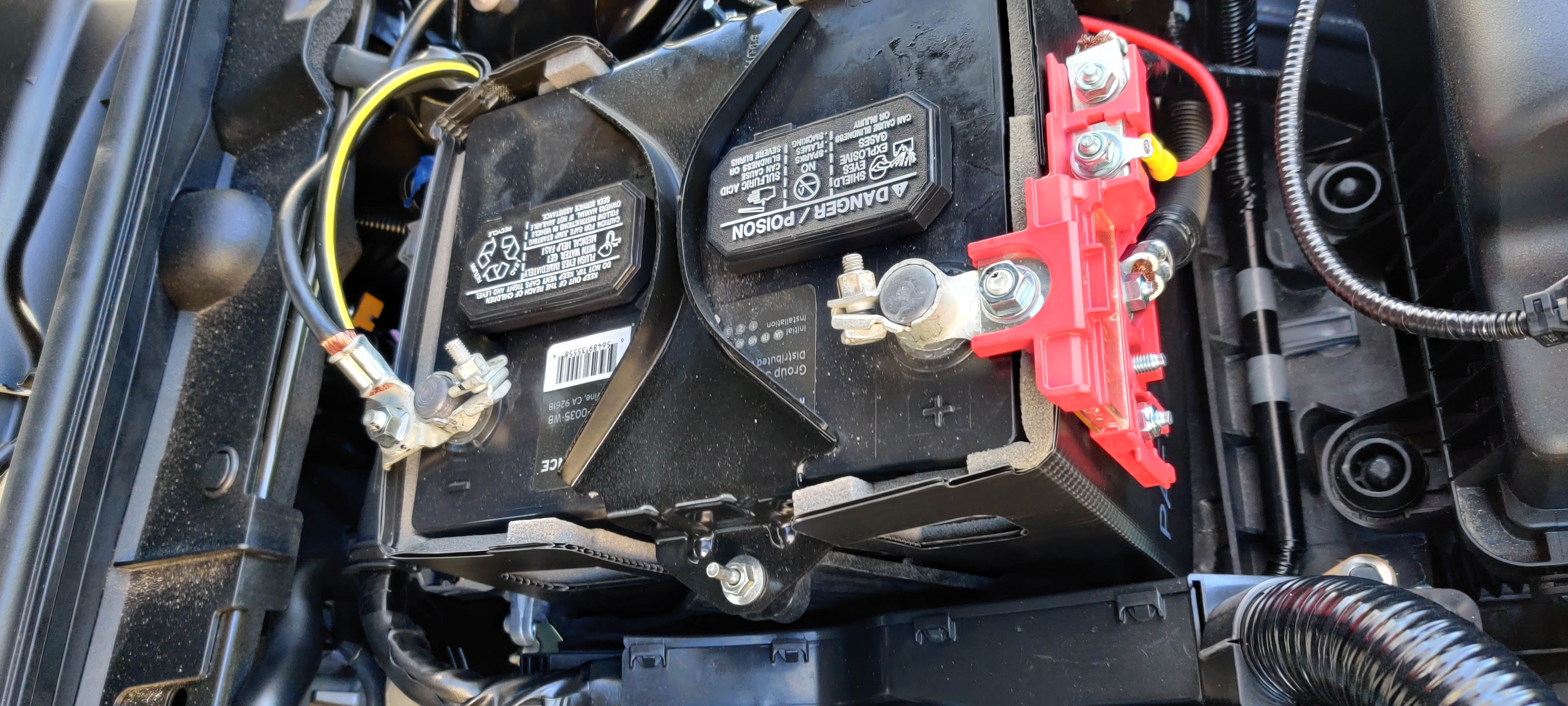
Battery with distribution block. The two bottom-most studs are both spare and fused at 80A.
With any project like this, getting through the firewall in a safe, clean, and watertight way is a challenge. I used a gasketed cable gland through a conveniently blank spot. I say convenient…I did have to remove the air filter box, the battery, the ECM, the battery tray, and much of the ECM harness to access the area from the engine bay, and had to slice through the carpet and soundproofing mat in the cab. But it went well and now I have a watertight penetration.
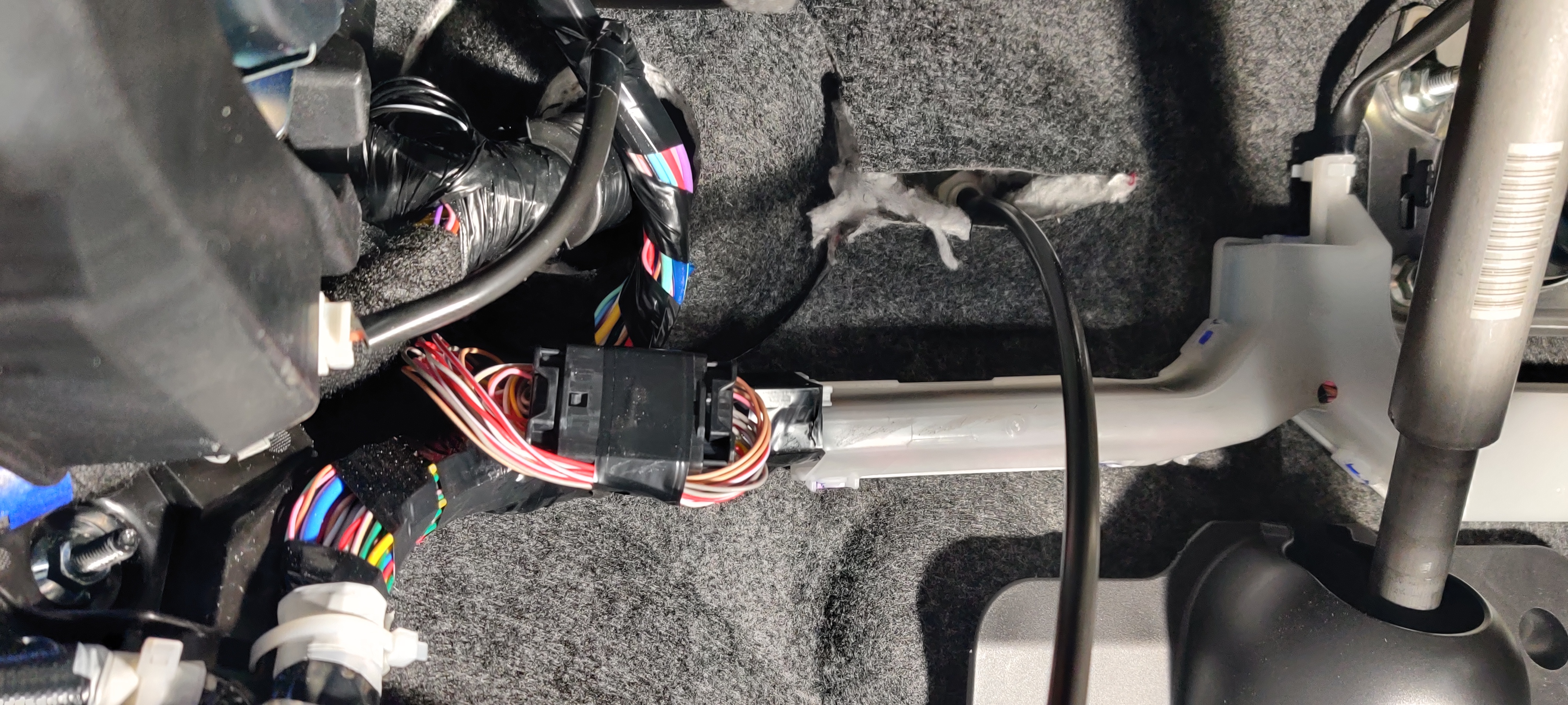
View of gland and cable inside cab. This is directly behind the instrument panel cluster.
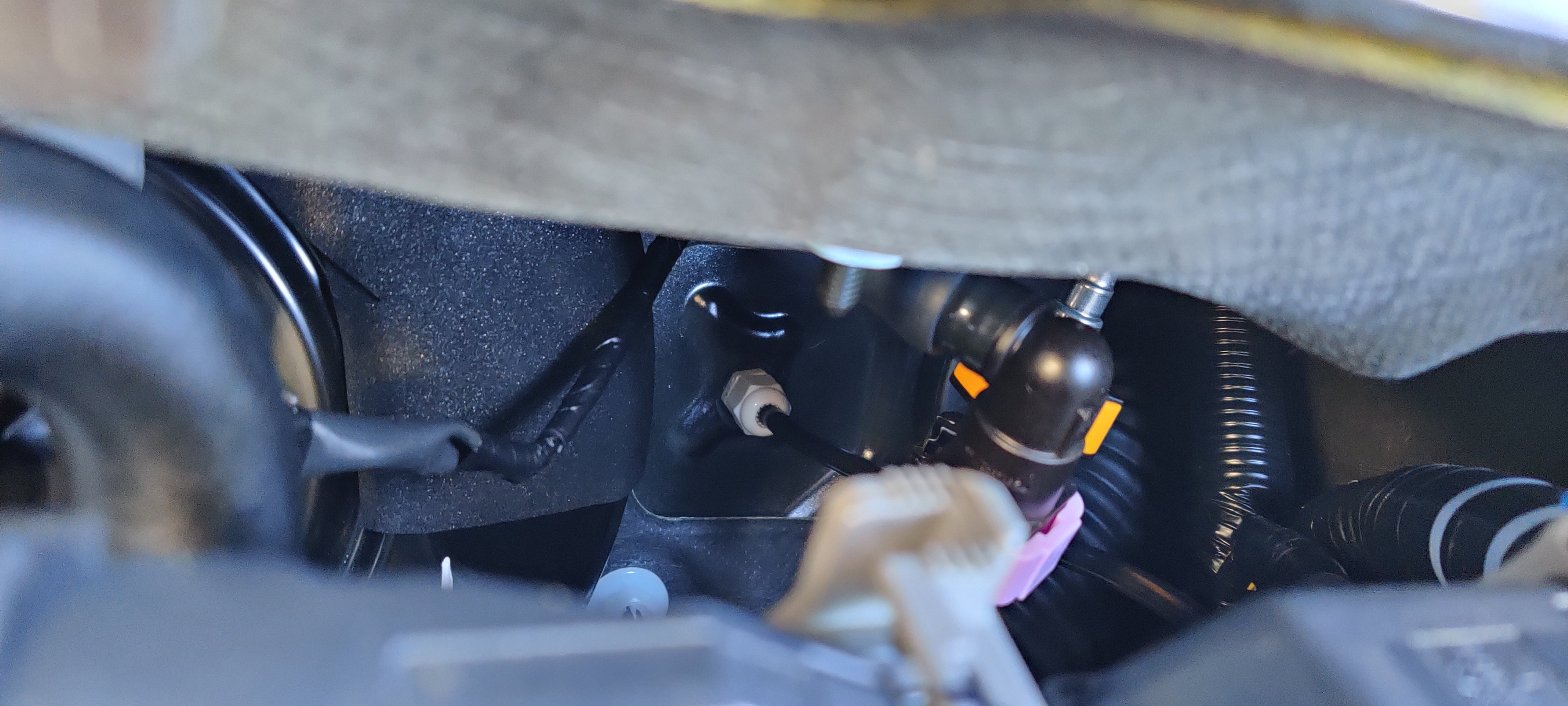
View of gland and cable in engine bay. This is directly behind the battery and ECM.
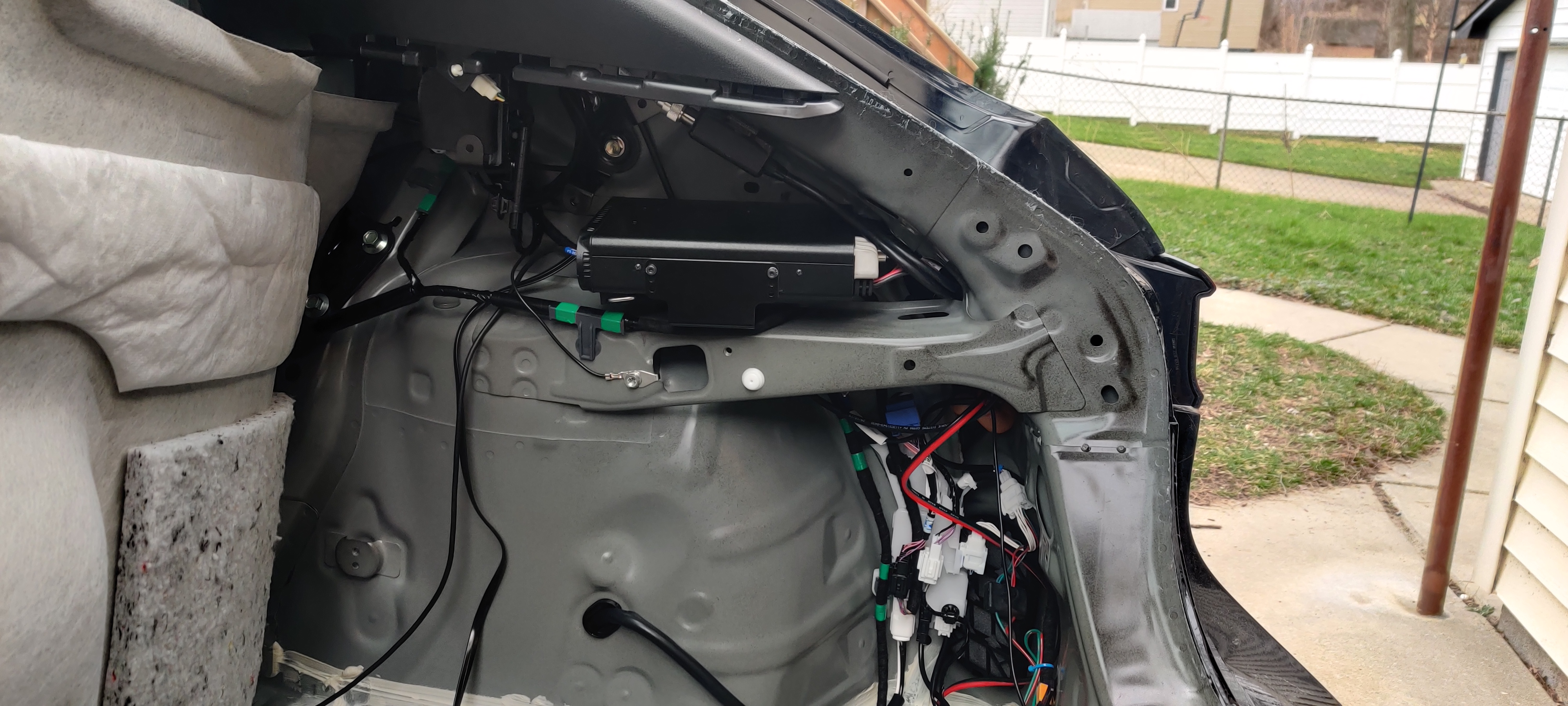
In the driver’s side rear quarterpanel, I lucked out. There is a wide-open area with a horizontal frame member forming a shelf, with plenty of space for my sub-panel and FT-8900R. I did have to relocate the “ELECTRICAL SUPPLY MODULE” off its bracket and forward, under the rear seatbelt reel, but I am confident this is OK.
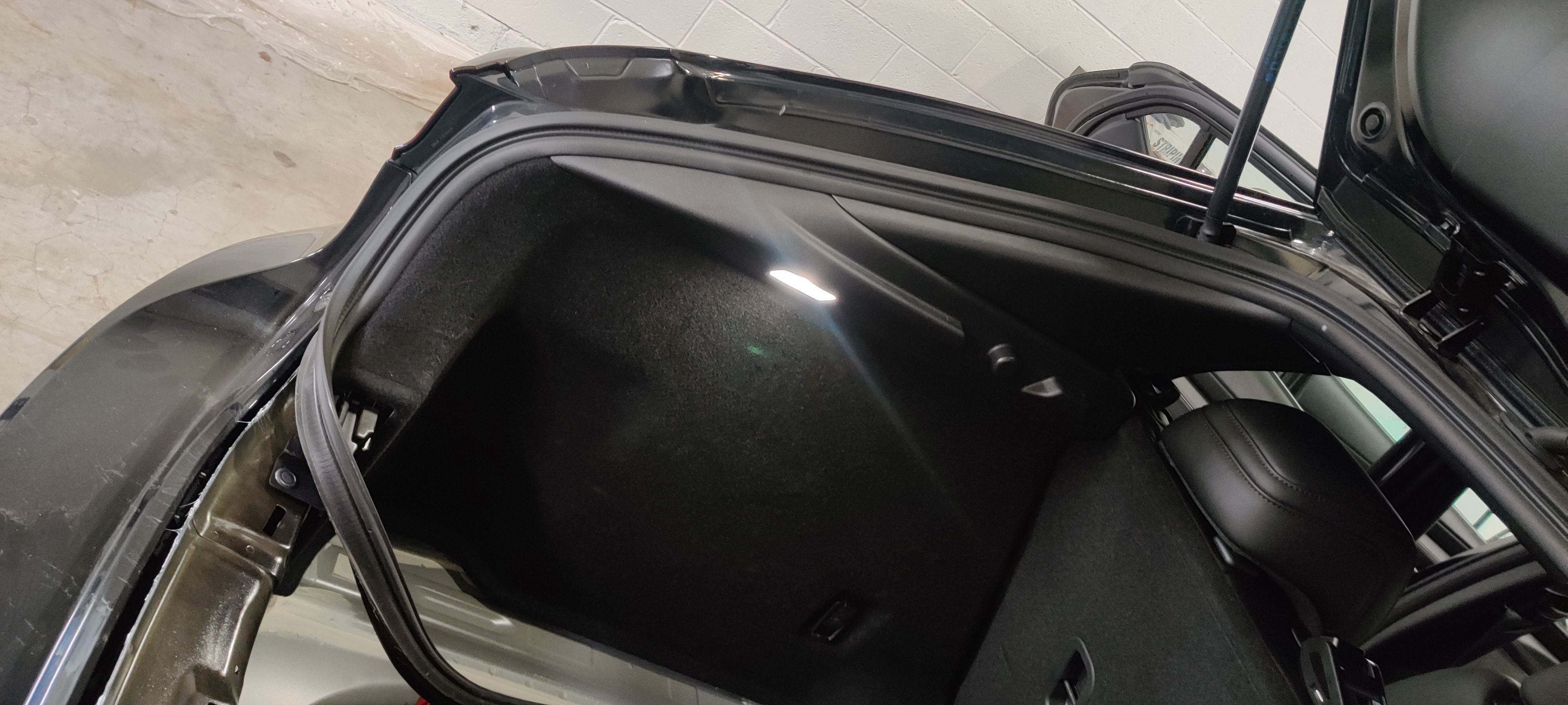
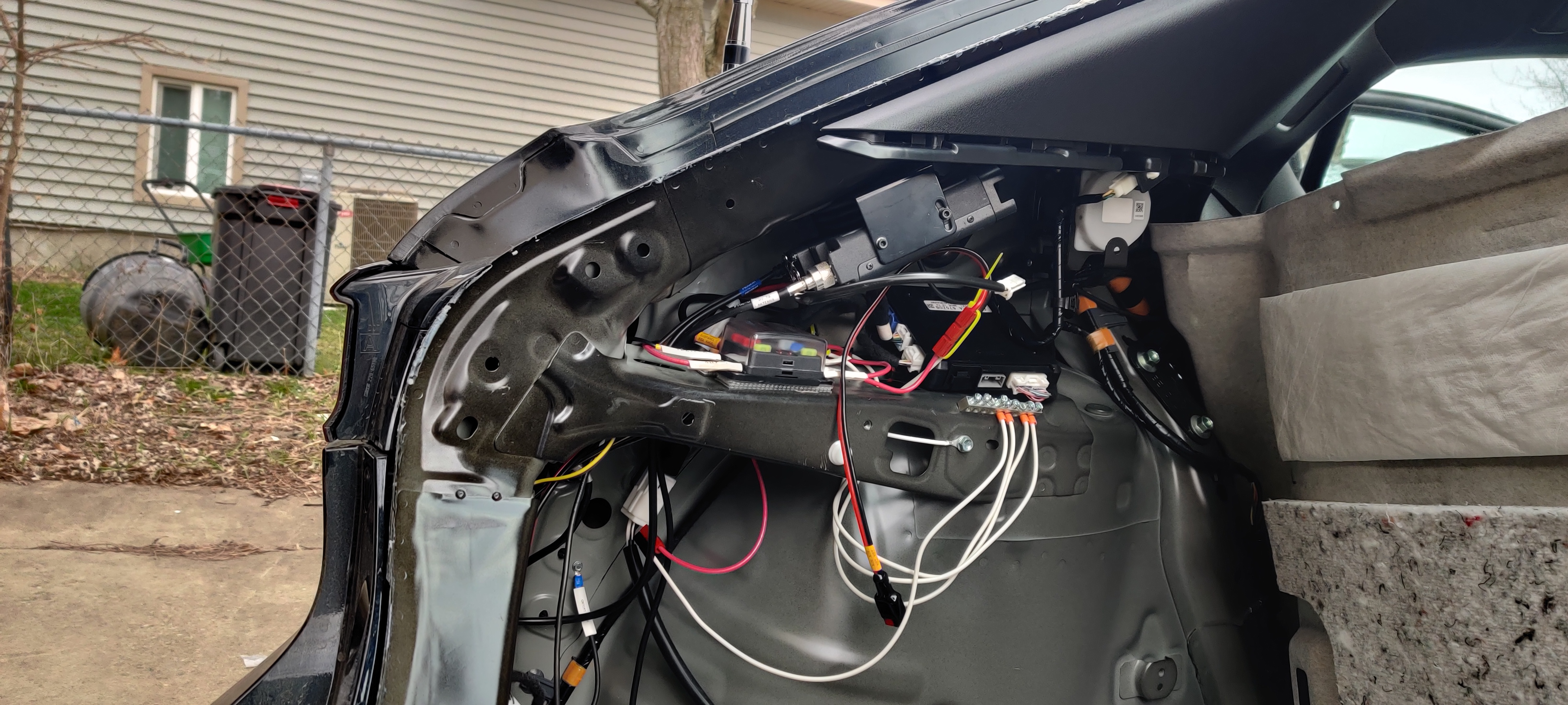
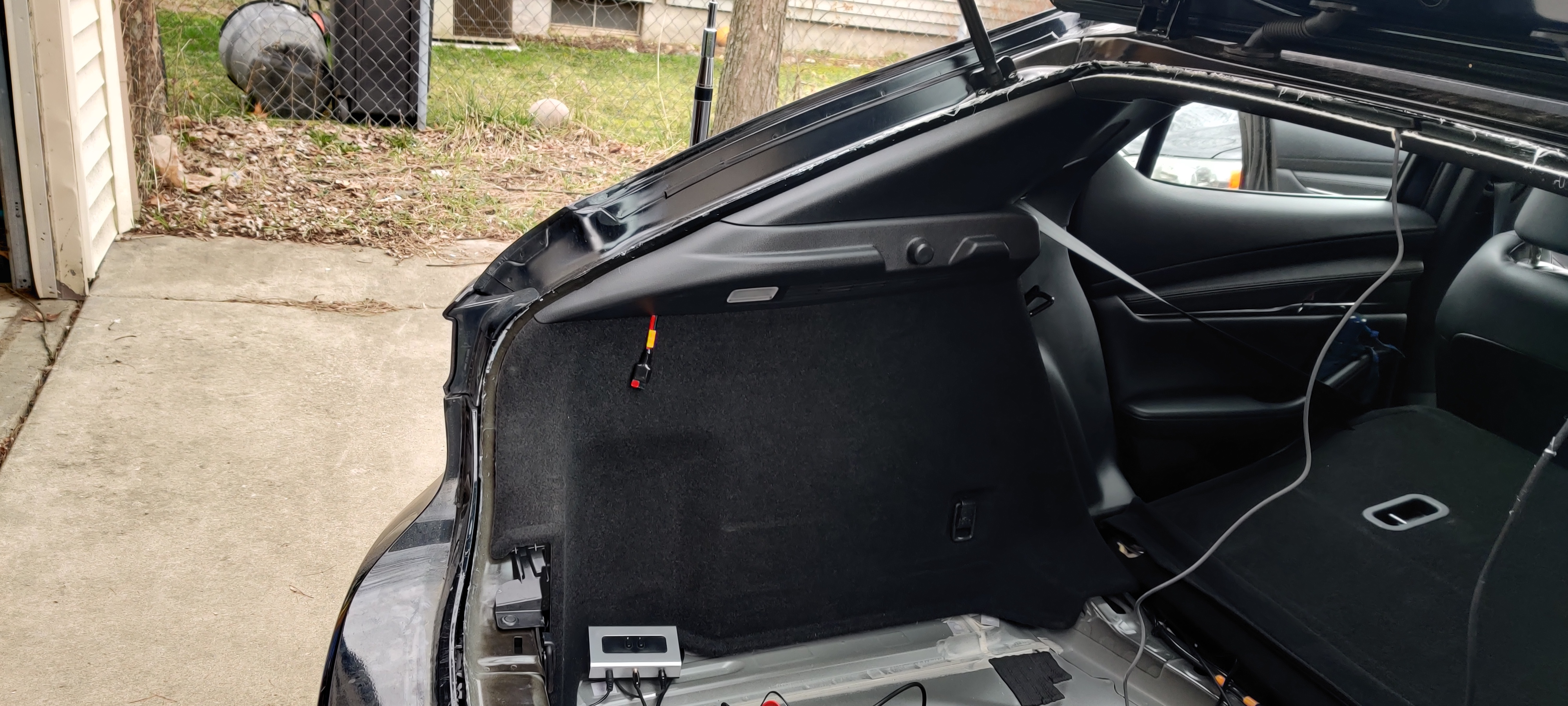
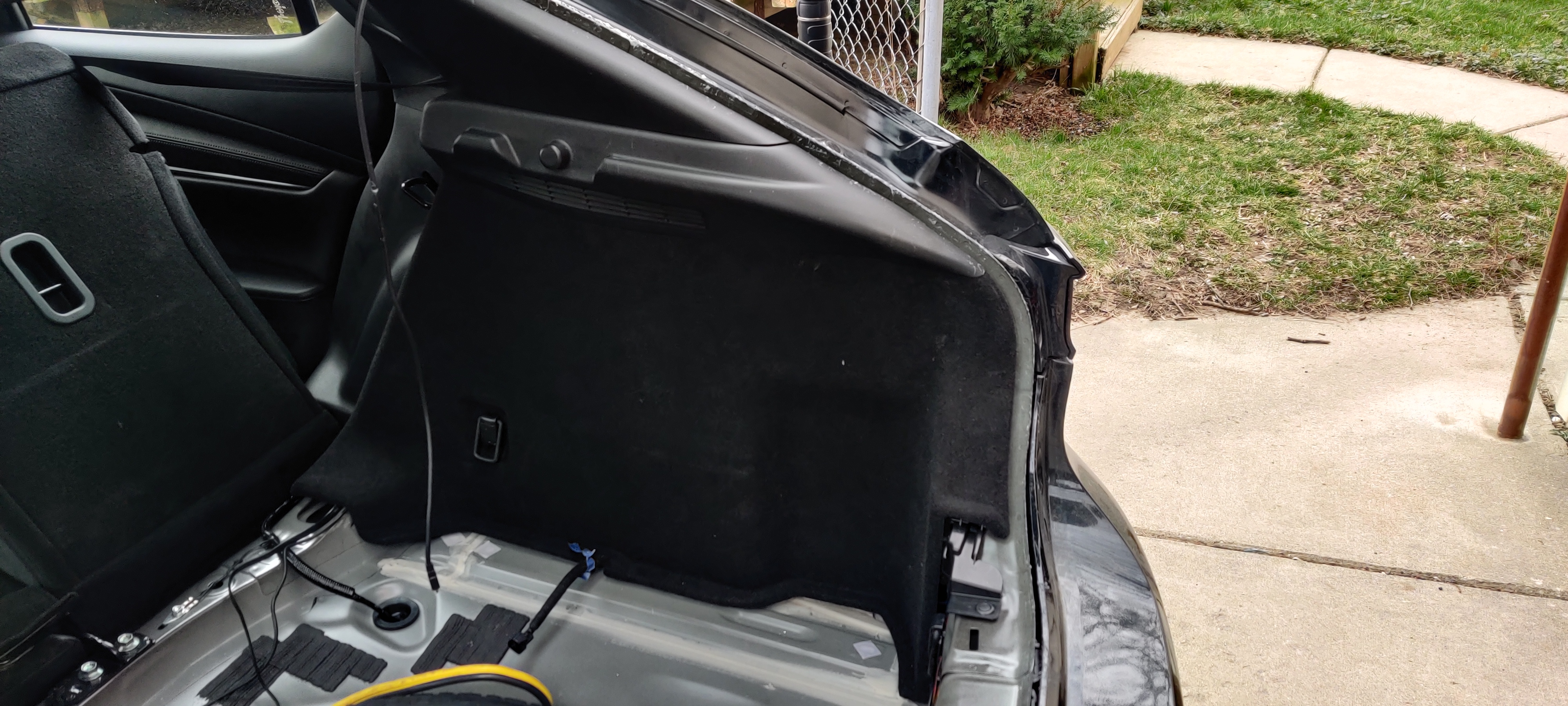
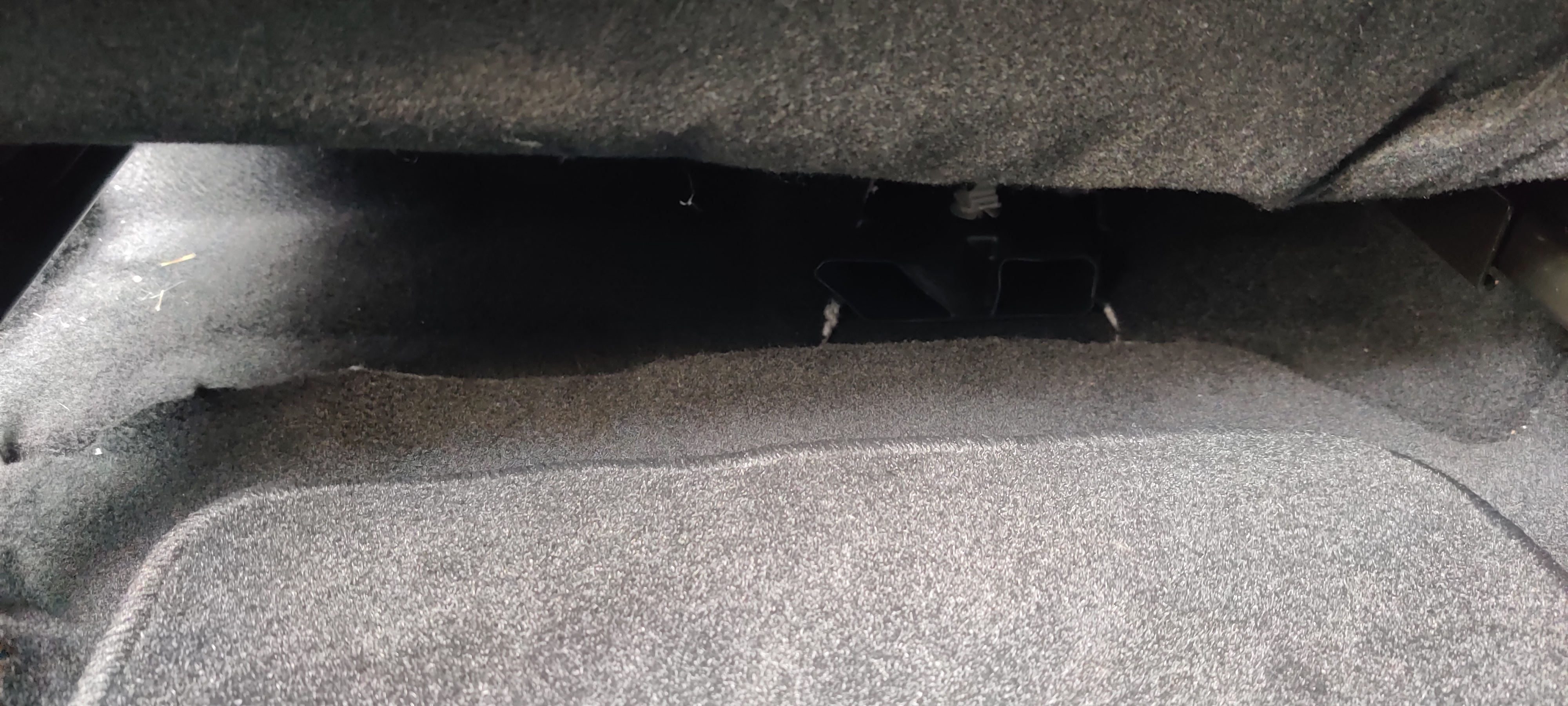
Driver’s side of hatch, with the LED for the cargo area. Behind this carpet is an astonishingly large free space…and soon a subpanel and radio…
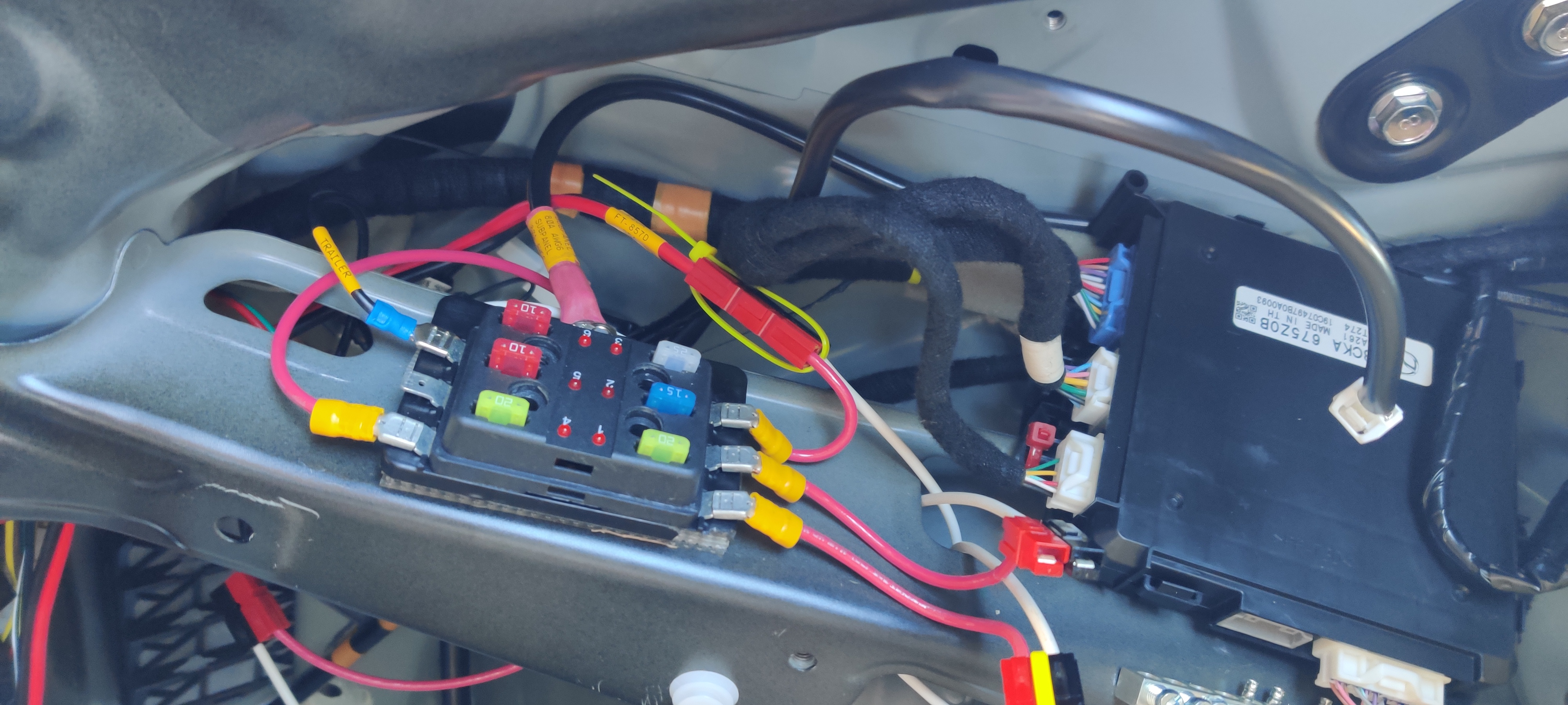
Driver’s side rear quarterpanel. The right-most black box is the OEM “ELECTRICAL SUPPLY MODULE”, relocated under the seatbelt reel. The subpanel is a cheap unit found at O’Reilly or similar.
Once the engine bay was reassembled, the feed was labeled and landed on the stud.
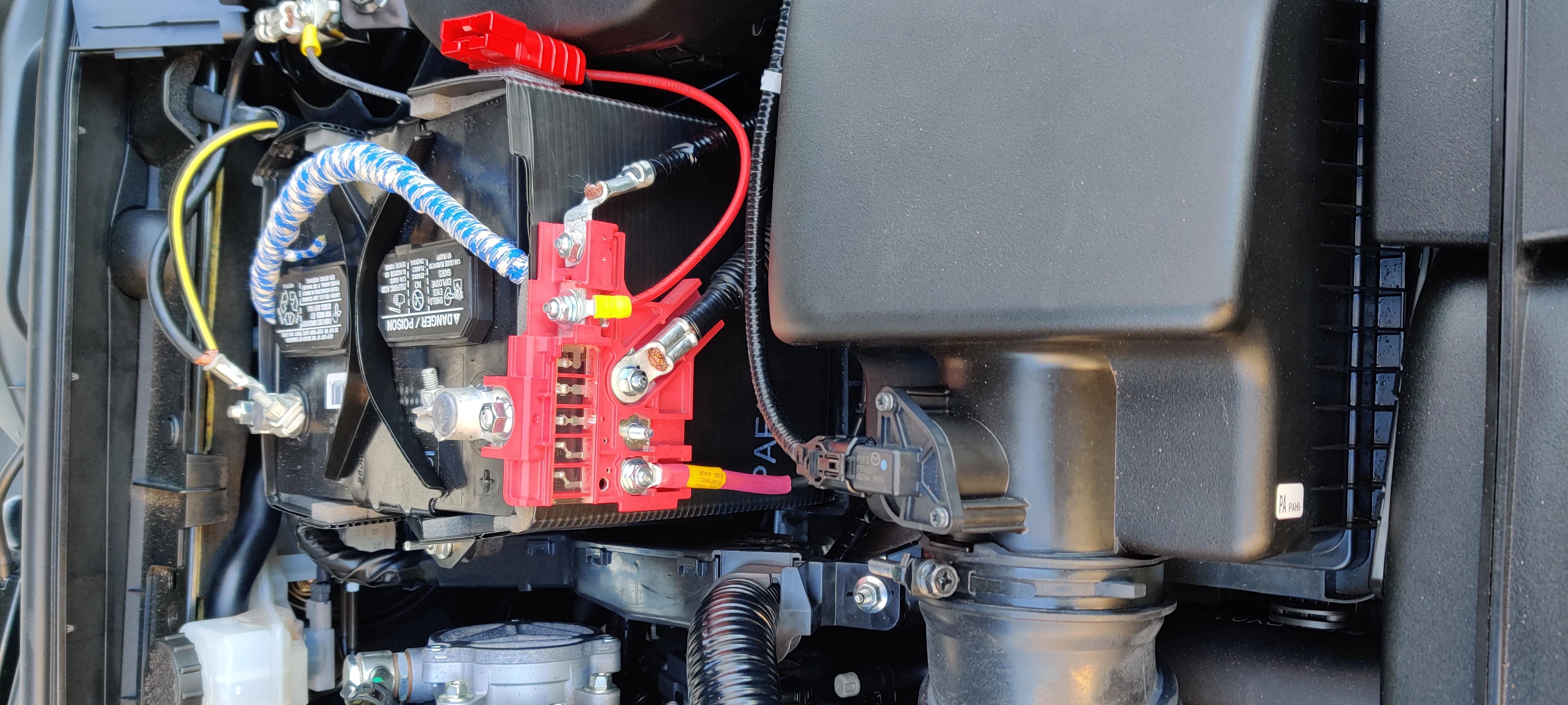
Engine bay, reassembled, with AWG6 feed to subpanel labeled and landed on 80A stud.
FT-8900R Installation
Now that I had power, I wanted to install my FT-8900R. This is an FM-only quad-band (70cm, 2m, 6m, 10m) dual-VFO/dual-receiver radio that is excellent at repeater work in the local area, matched with the HV-7A antenna.
The FT-8900R is a ridiculously compact radio, and gets even smaller with the head detached on the separation kit. With the mobile mounting bracket, the whole radio fits flush behind the carpeting on the diagonal frame rail over the shelf. Three #8×1/2″ sheet metal screws hold the bracket in place.
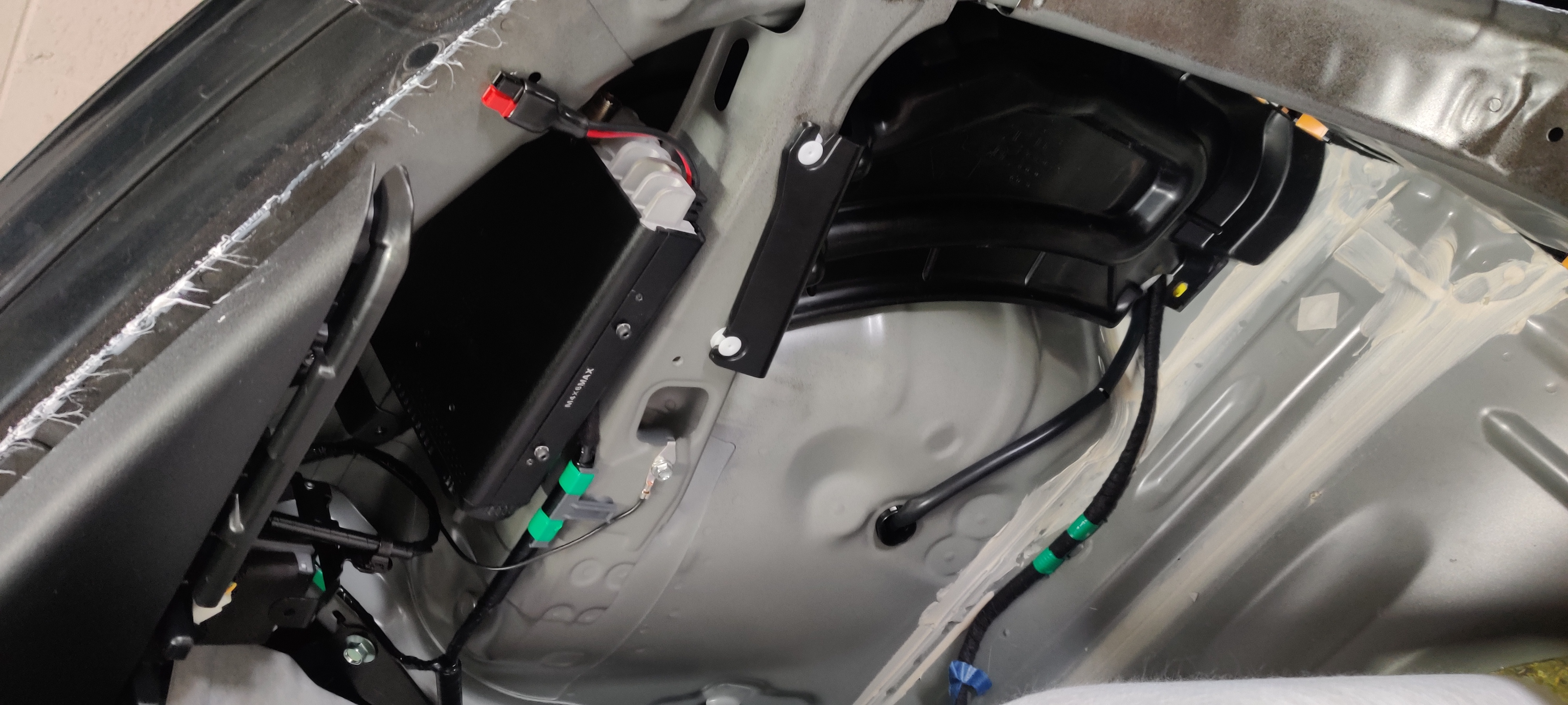
FT-8900R mounted on diagonal frame rail over shelf and subpanel. White flying connector is for cargo area LED; flying PowerPole is 20A auxiliary for cargo area. Ziptied PowerPole over OEM module is feed for FT-857D on the other side of the car; the one under the FT-8900R is for that radio.
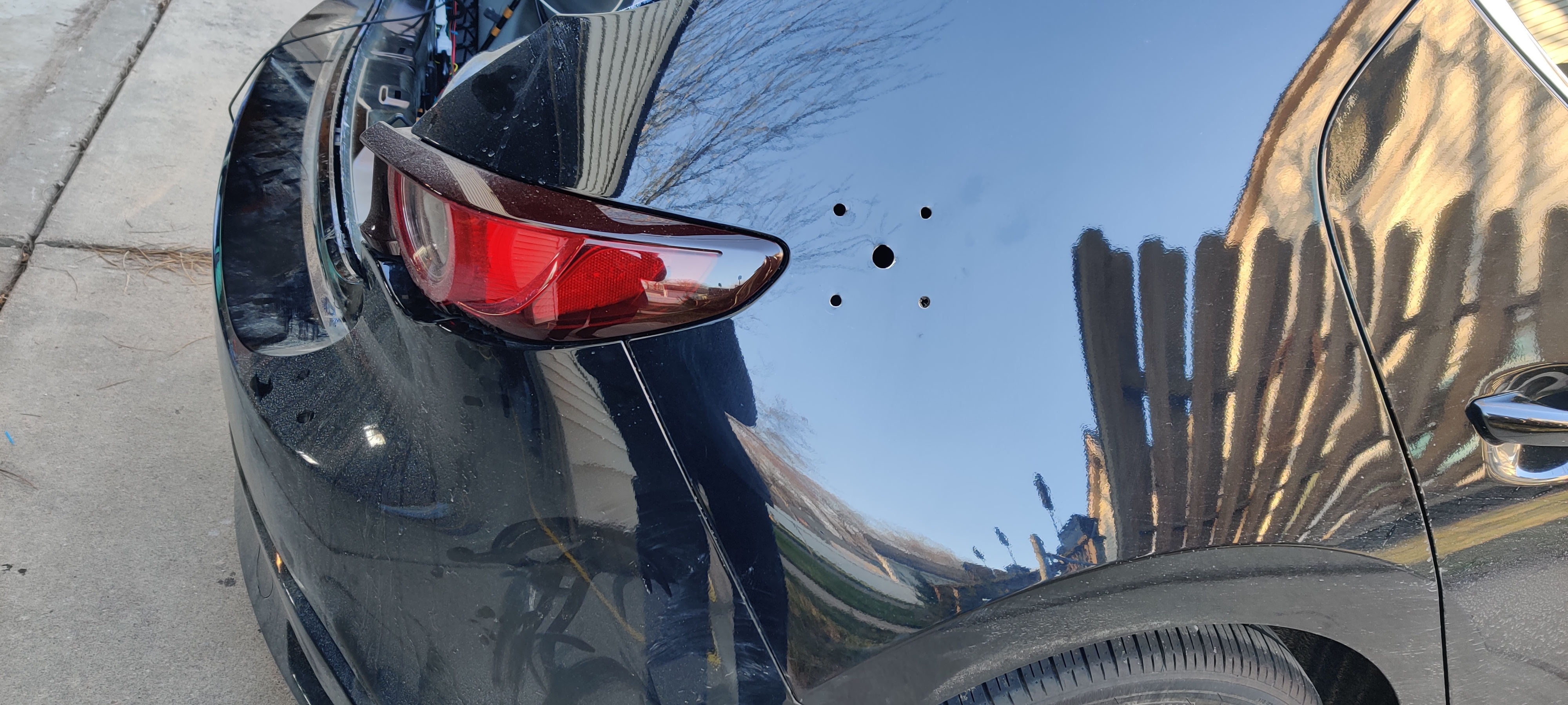
I eyeballed the placement of the Breedlove mount so the ball was centered between the fuel door and the combo light, then marked out the holes. Pucker factor 100% drilling holes in brand-new body panels. A quick deburr inside and out, and it was time to pull the panels together…whereupon I had an issue. The inside frame members were too close to the outside panels for me to reach the holes. Fortunately, I also really like rope (get your minds out of the gutter; I am a sailor and taught Pioneering merit badge for years through my BSA career). I threaded some light line through the holes and grabbed it inside the car, then tied it through the backing plate with a slipknot. Careful feeding of plate and knot into the interstitial space and I could pull the whole plate flush and aligned with the outer holes.
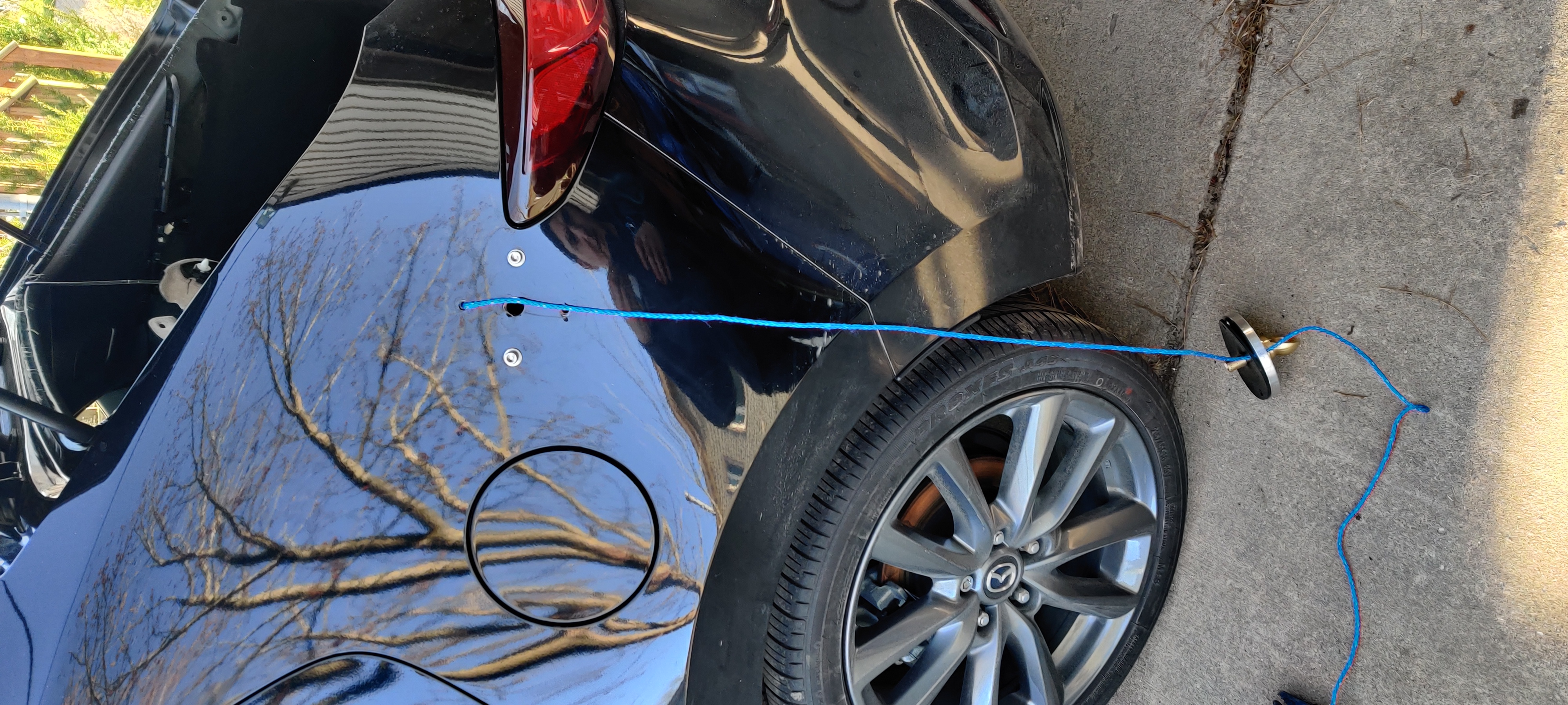
A clever fishing expedition, pulling the backing plate of the Breedlove mount against the inside of the body panel so I can get the two plates aligned with each other and the body panel.
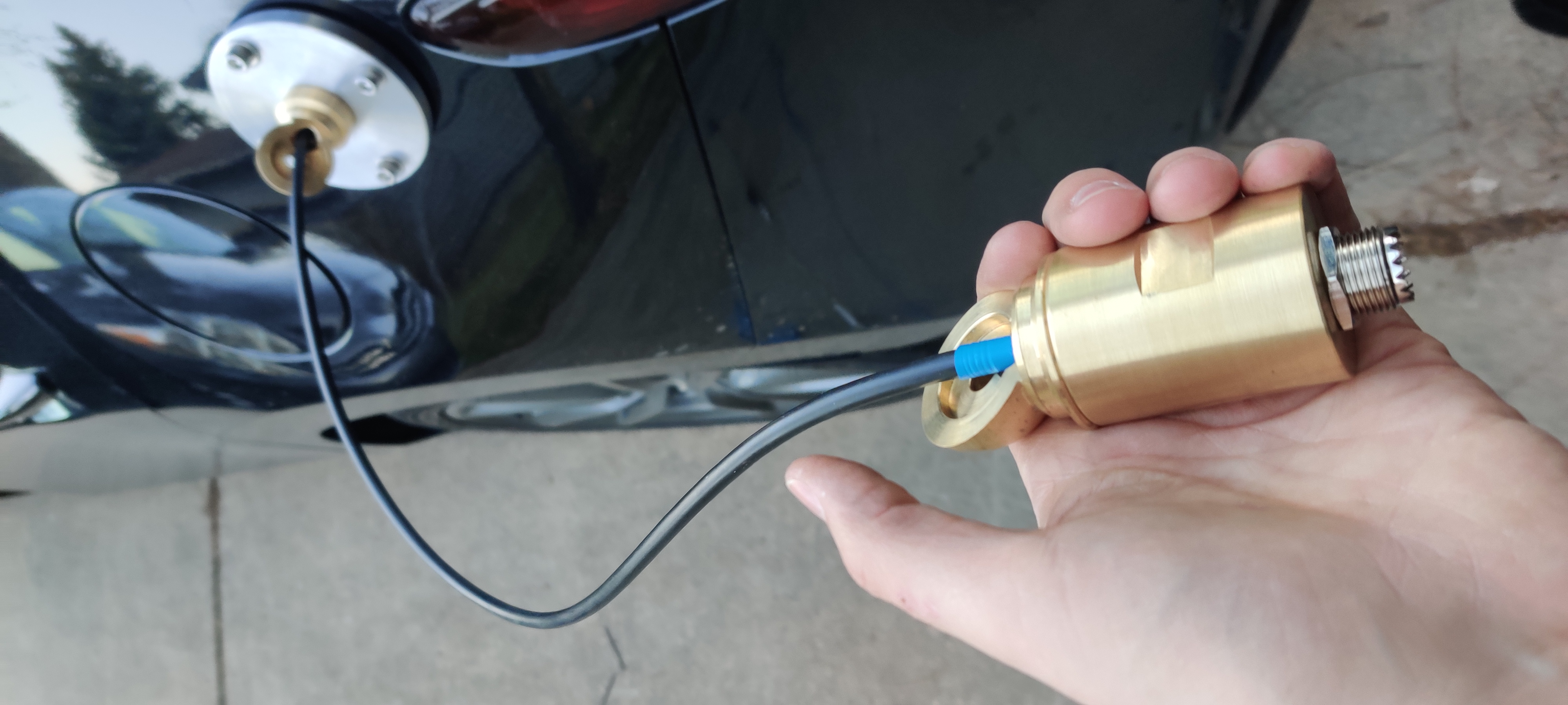
Fishing the LMR-240 through the ball and inner shaft, into the cargo area.
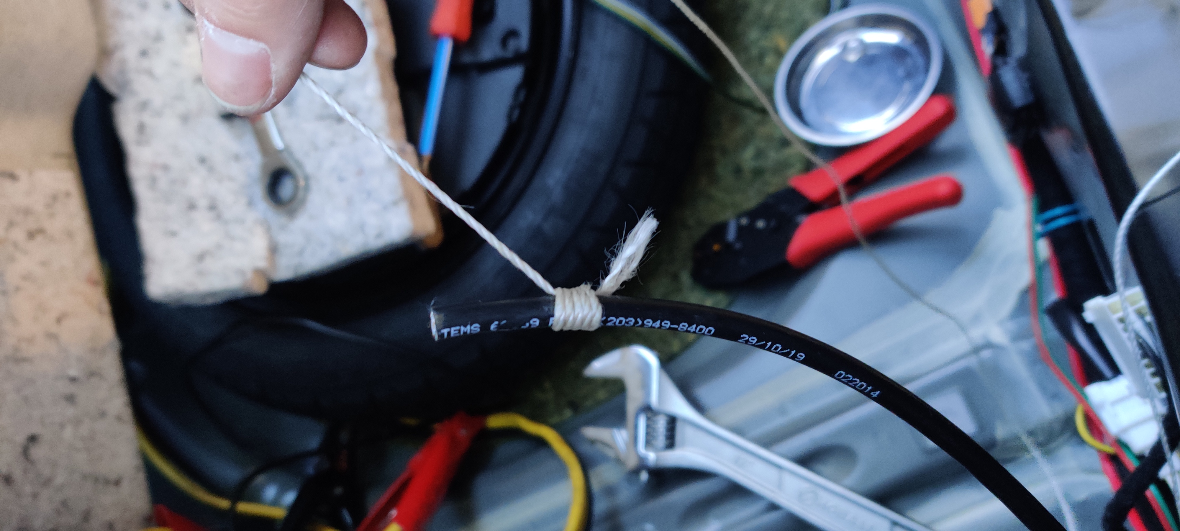
All that time in the Scouts really paid off; a traditional whipping bites well enough on the coax to act as a non-damaging pull.
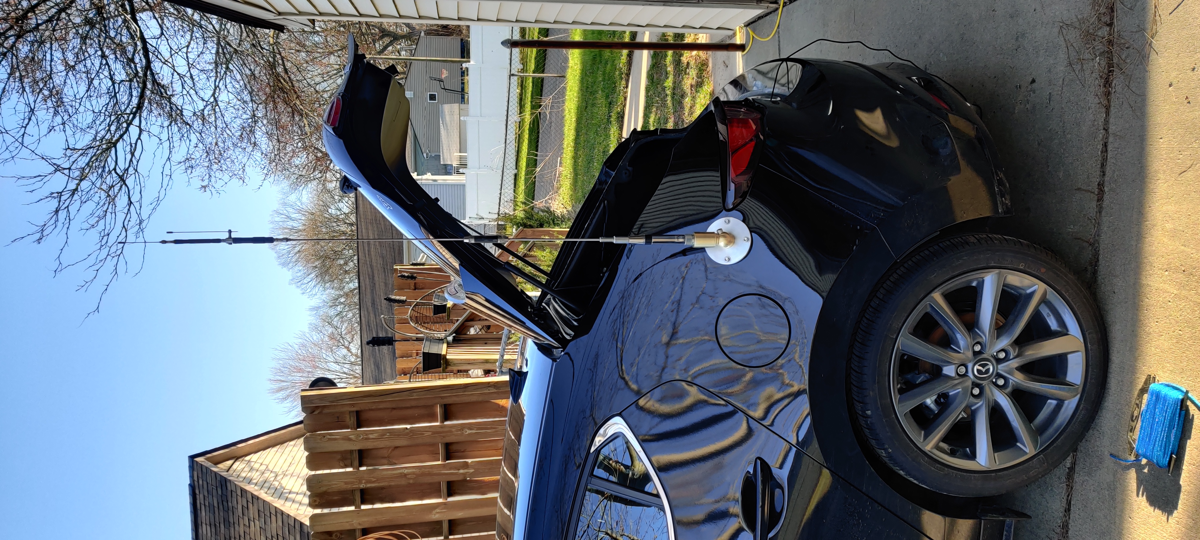
Completed mount with HV-7A standing proud and plumb.
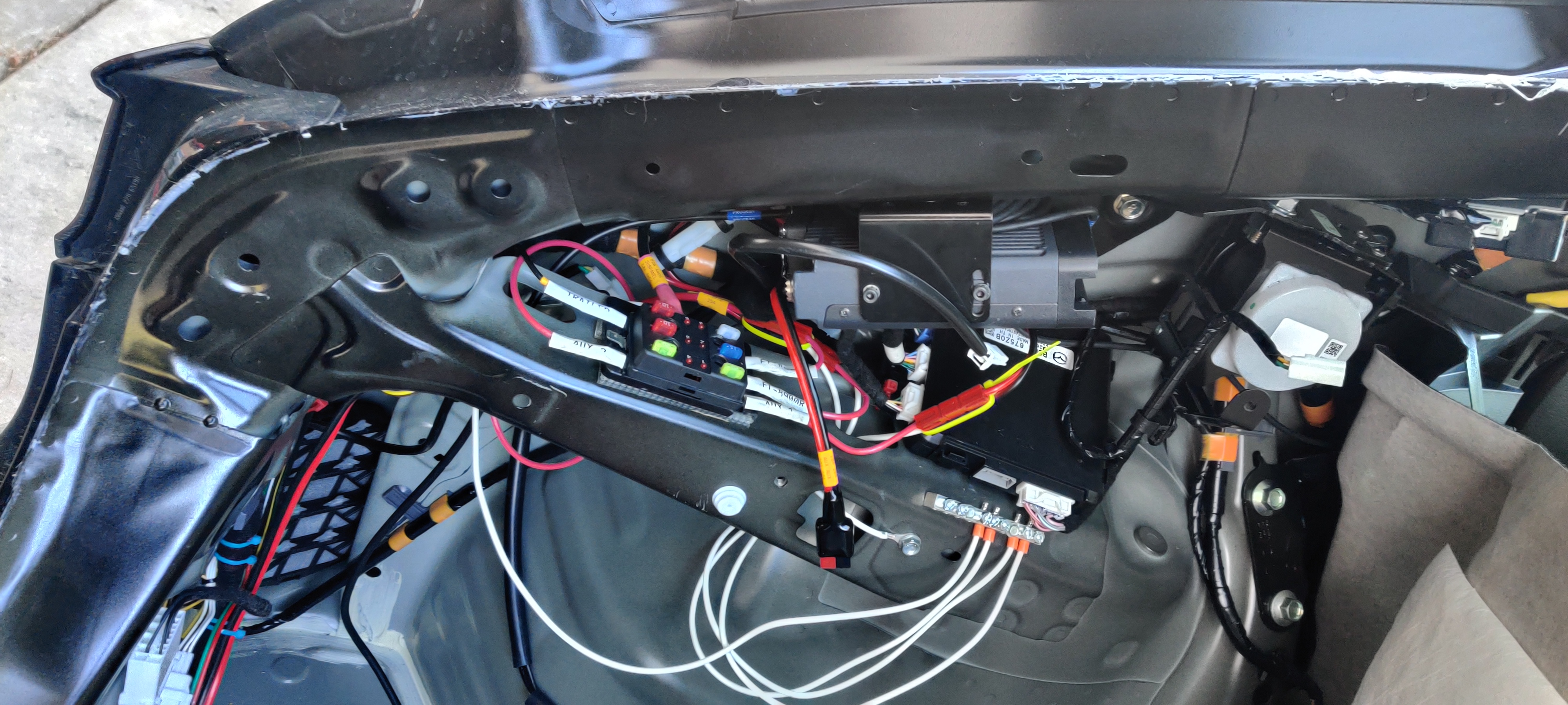
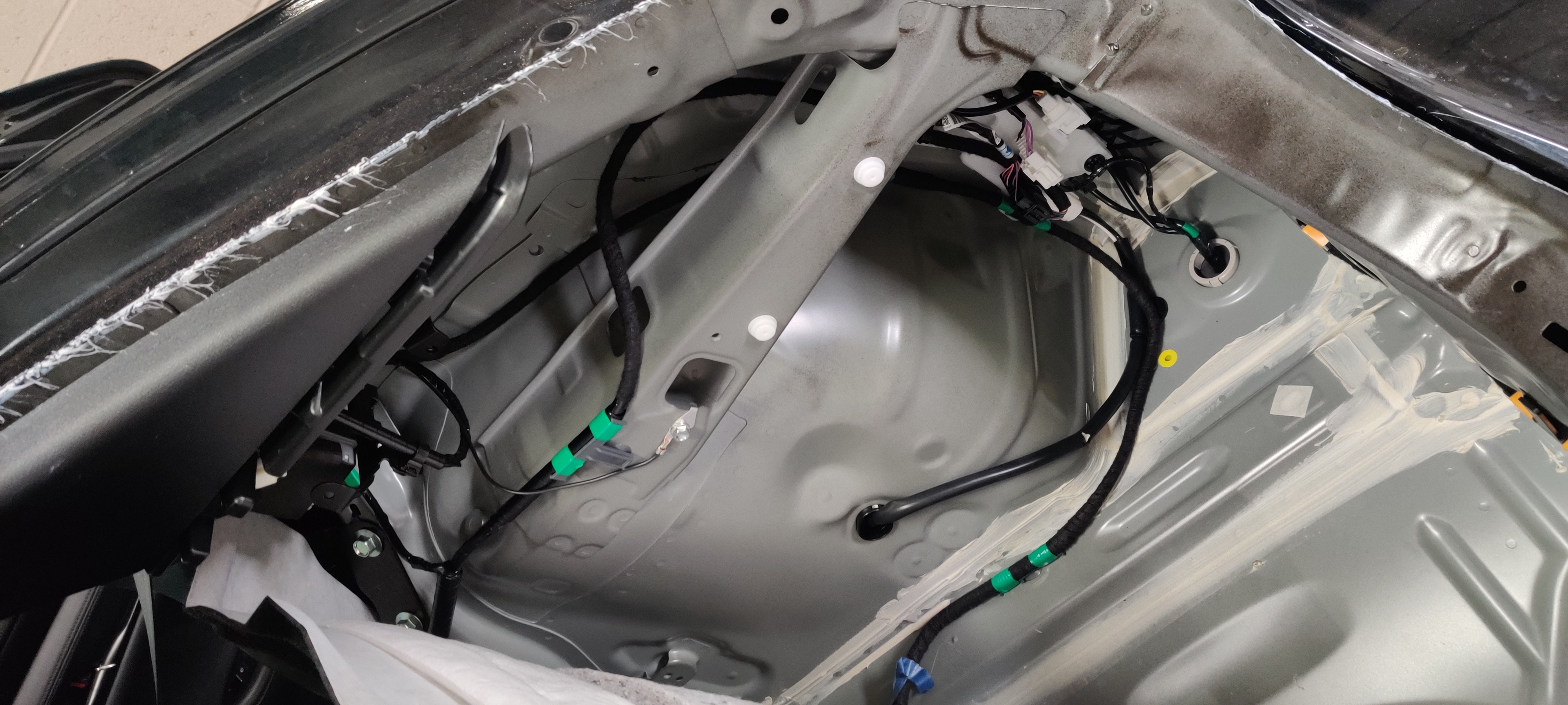
Completed installation, with coax labeled and terminated. The backing plate for the mount is approximately behind the triangular gap formed by the FT-8900R and the OEM module. All access was through a narrow slit aft of the inner frame member, shown with a large knockout and the Breedlove grounding wire.
With everything installed and confirmed working, I ran the separation cable into the passenger area, a programming cable extension into the cargo area, and an external speaker cable into the cargo area, and buttoned everything up.
Driver’s side rear quarterpanel, now with radio and subpanel installed. Note the 20A PowerPole drop tucked under the cargo area LED, and the 1-2 switch for external speaker (soon to be replaced with an actual mixer). Not shown (because framing!) programming cable extension.
FT-857D
Next up, the FT-857D. This is an all-band (something like 1MHz through 700MHz) all-mode (AM, FM, upper sideband, lower sideband, packet and digital modes) dual-VFO/single-receiver radio that is excellent at longer-range things and packet digital work, matched with the motorized tunable ATAS-120A antenna.
The FT-857D is nowhere near as compact as the FT-8900R, even with the separation kit. With the mobile mounting bracket, the radio does bow out the carpeting when mounted horizontally on the shelf inside the passenger side rear quarterpanel. Two #8-32 bolts and Nylock nuts hold the bracket in place.
Passenger side rear quarterpanel has a similar shelf arrangement as the driver’s side, but no OEM module to deal with.
FT-857D mounted, with bonus appearance of soundproofing plug for interstitial space.
Mounting the antenna was much the same as for the FT-8900R, but I actually measured the mount position so it matched.
Five mounting holes for the Breedlove mount. The central one is 5/8″ and accepts the brass inner shaft for the cable; the outer ones are 11/32″ for the mounting bolts.
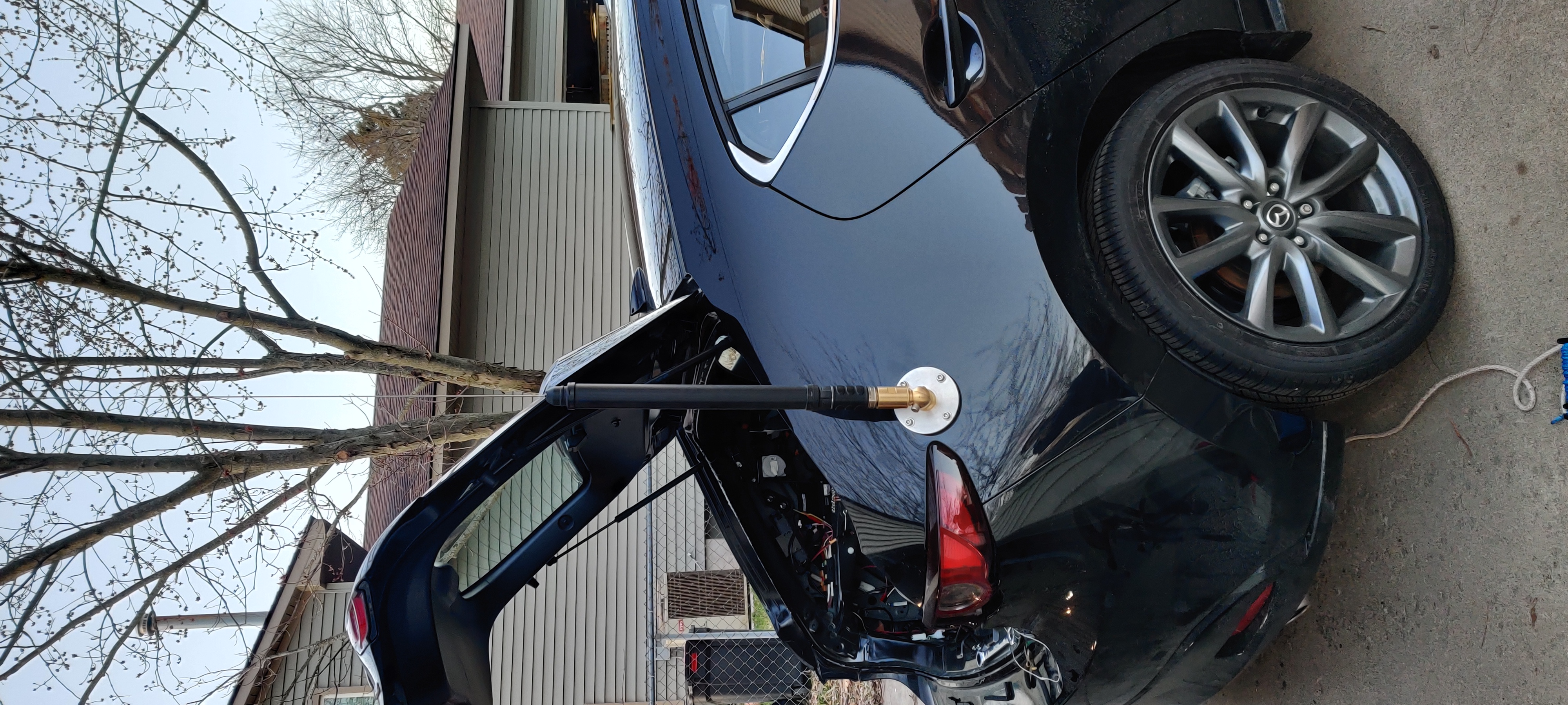
ATAS-120A mounted proud and plumb
When everything was tested, I could not get any reception on KEC63 (this station broadcasts from the National Weather Service in White Lake on a frequency of 165.55MHz...). Which, you know, bad.
So I cut the connector off and redid it. Everything good the second round; I think I got some of the braid into the center conductor the first time around.
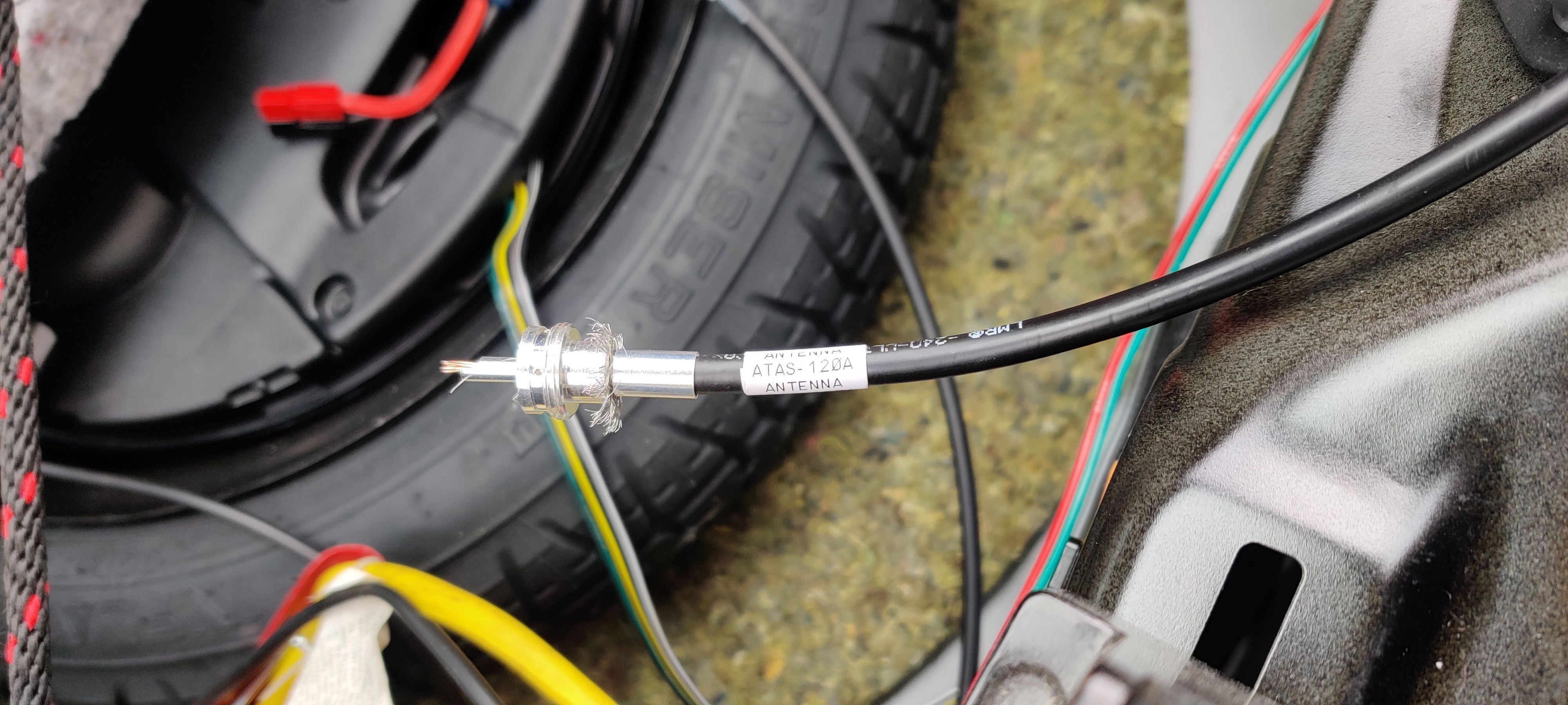
In-process round two of PL-259 connector for the ATAS-120A.
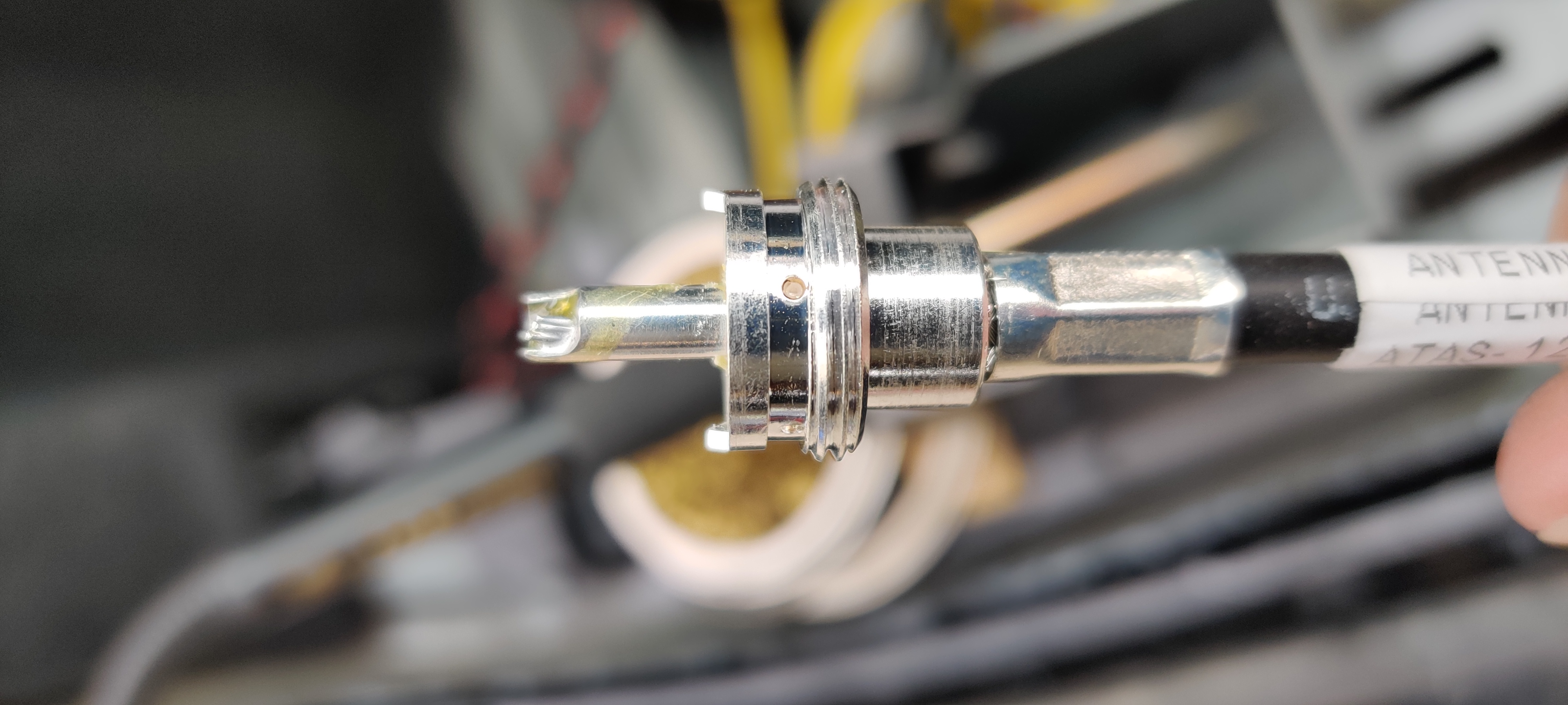
Completed (and working!) PL-259 connector.
Once everything tested out OK I mounted the CF-706 duplexer, ran the separation cables into the passenger area and an external speaker cable into the cargo area, and buttoned everything up. (No programming cable extension yet; it is in the mail still, along with a Bluetooth adapter from KC8UFV).
Completed installation. Note how little space behind the radio there is for cabling. Also note the CF-706 duplexer mounted above the radio on the diagonal frame rail.
Just the barest hint of a curve in the vent panel over the FT-857D. Otherwise, buttoned up just fine.
Interfaces
Inside the passenger area, it was time to figure out where the heck I was going to put two microphones and two heads. In Matilda, I had the FT-8900R head mounted under the dashboard near the door knee panel, and that worked well. It fit right over the hood release lever and below the random little storage compartment Mazda bequeathed the 2019 with.
FT-8900R head shown under dashboard, just above the hood release lever.
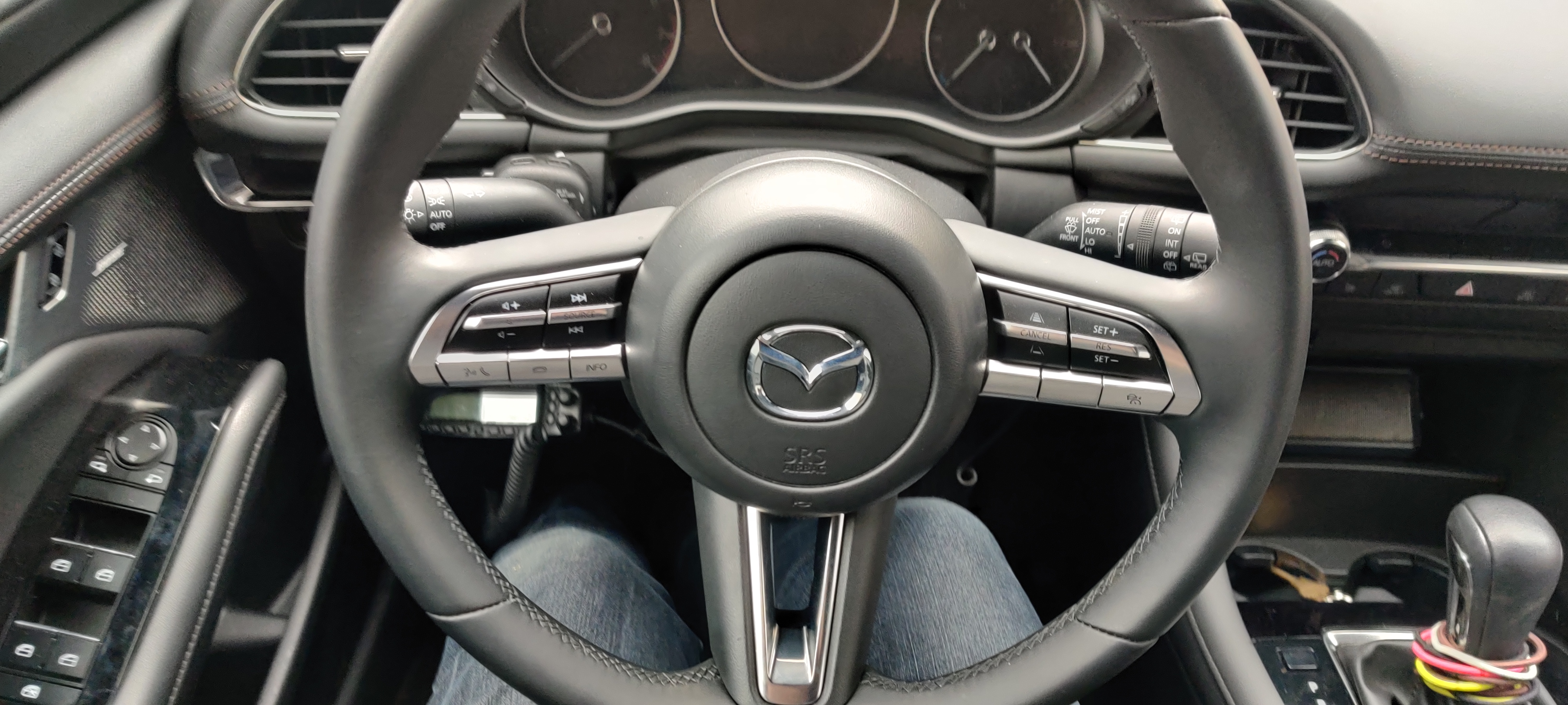
The cabling for that and the microphone for the FT-857D were pulled through the driver’s side door sills and up behind the inside OEM fuse panel. The FT-857D mic is the lesser-used one and got a clip on the left side of the steering wheel; the FT-8900R is the daily radio and got a clip on the right side next to the pushbutton start.
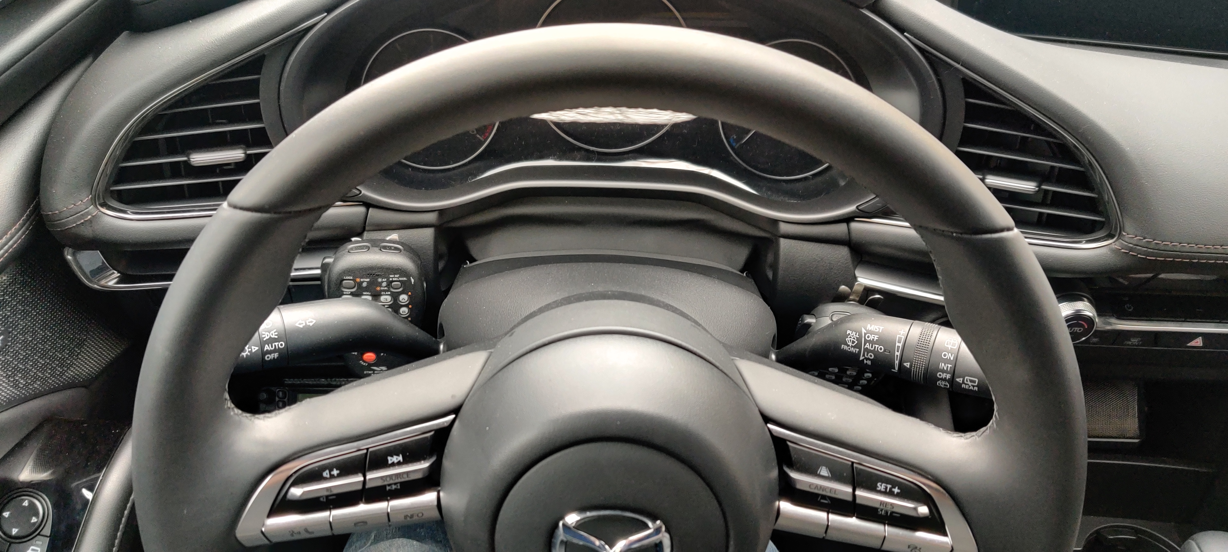
Overhead shot showing both mics nestled around the steering column.
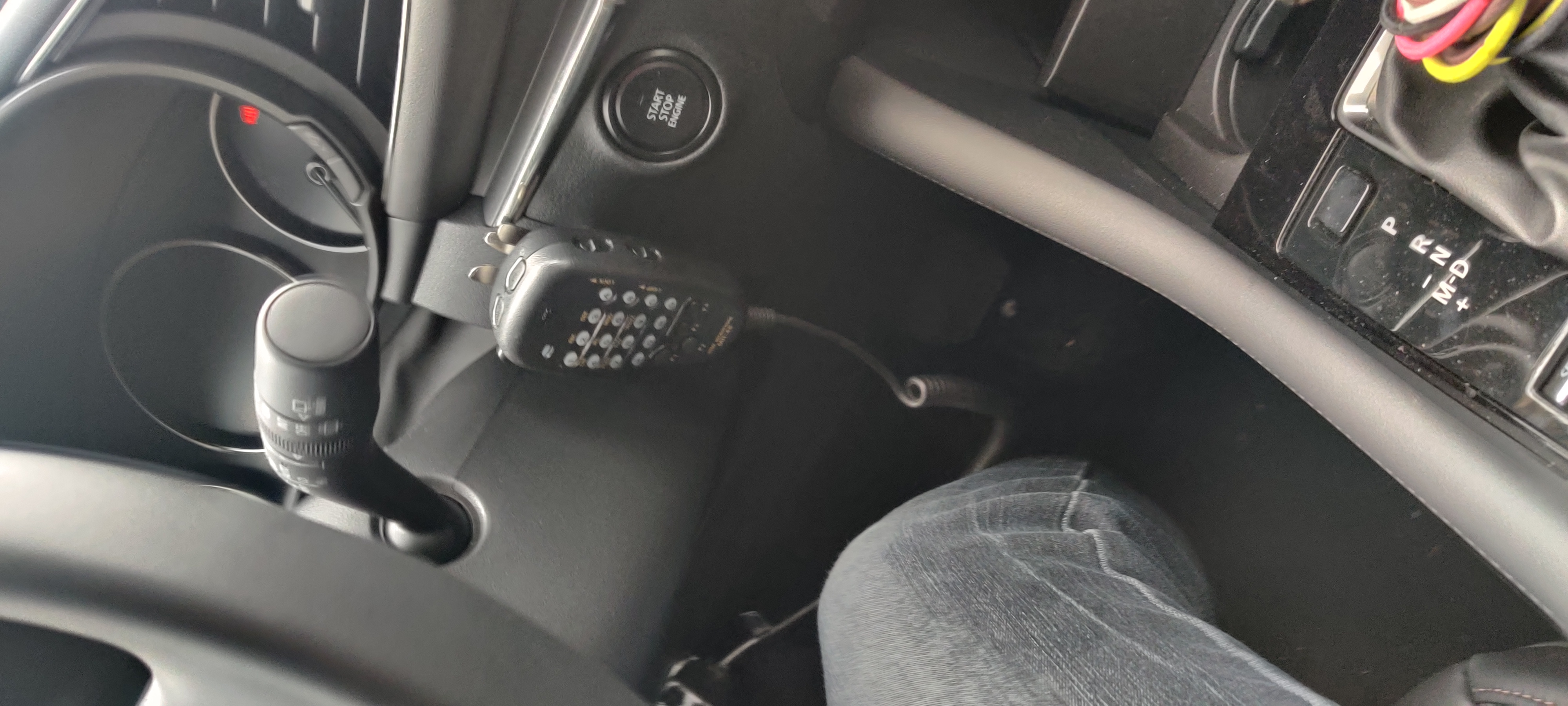
FT-8900R mic on right side of steering column, next to pushbutton ignition.
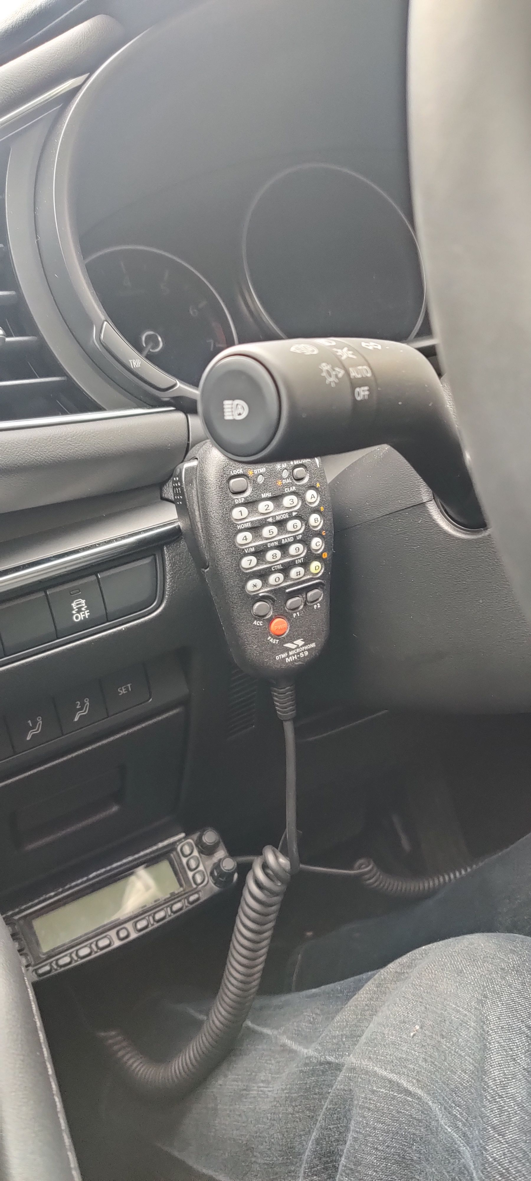
FT-857D mic on left side of steering column.
Now, where to put the FT-857D head? On Matilda, I mounted it front and center on the dash, just under the infotainment screen and vents. However, Minerva’s dash is laid out differently, the cupholders are up there in the way, and absolutely everything is covered in leather that I am loathe to drill holes in.
So I put the head in the much-expanded center console storage area. Some DualLock holds it to the wall, it is set low enough the console cover slides over cleanly, and just a little plastic notching and the cable runs cleanly under the trim panel, down the side of the console, and under the carpet under the driver’s seat to the door sills, where it joins its sister cabling back to the rear quarterpanels.
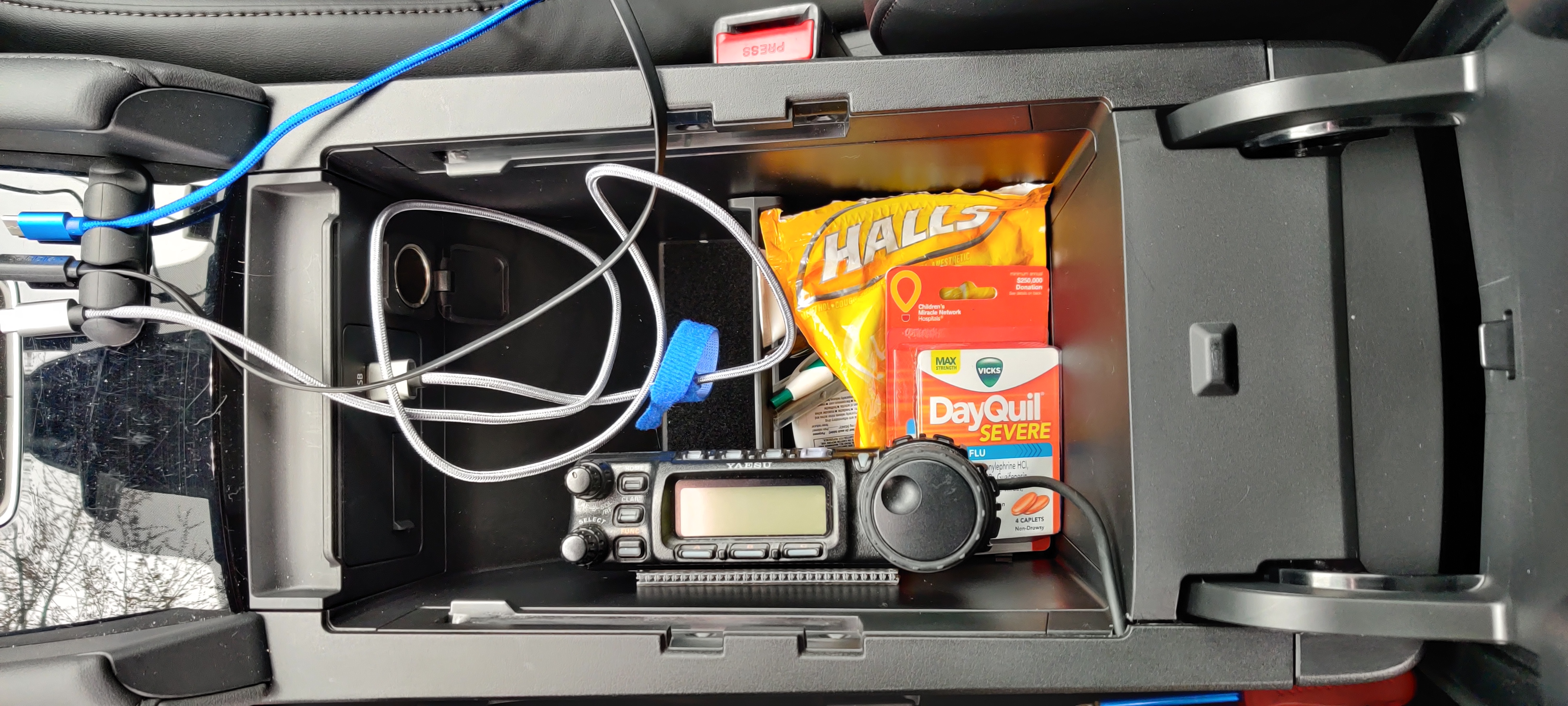
FT-857D head mounting inside center console storage bin. Note the one and only accessory port in the car, and the cable neatly going under the trim panel…
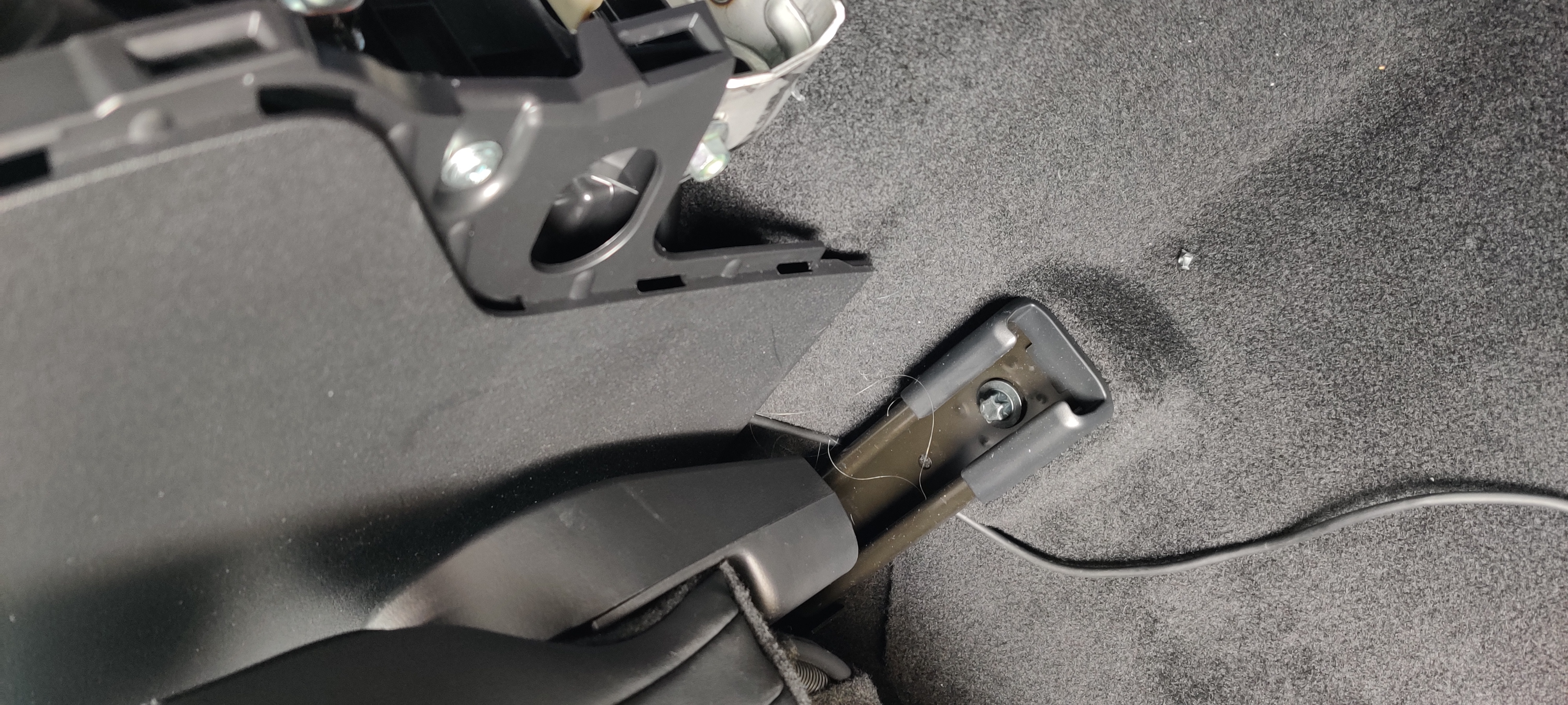
…which then runs down under the panel to the floor, to go under the driver’s seat…
…and under the carpet under the seat to the door sill, where it heads back to the rear quarterpanels.
Speaker
With the radios hidden behind much of the soundproofing in the rear of the car, they really need an external speaker. On Matilda, I had this “hidden” behind the infotainment screen. However, again, Minerva’s dash is all leather and laid out differently, so that option is just bad.
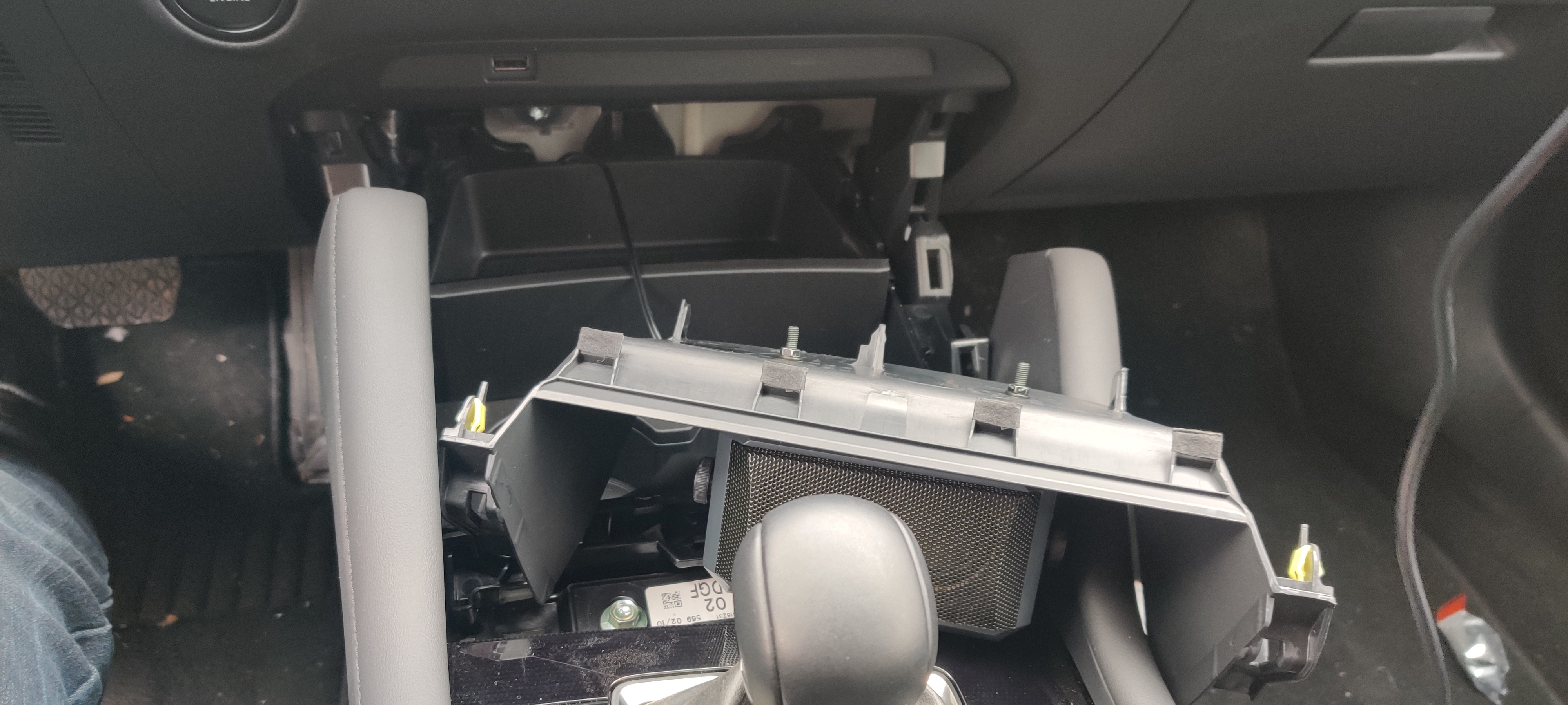
However, there is kind of a useless open storage area under the HVAC controls, forward of the cupholders. Some (OK, a lot) disassembly of the center console later, and I had the whole cupholder/storage/valence module out. A few holes drilled into the valence for the bracket, and another careful cable notch in the edge, and the whole thing reassembled into place. The cable runs through the console to meet up with the FT-857D head separation cable, and then back to the rear quarterpanels to meet the 1-2 switch (and eventually the mixer).
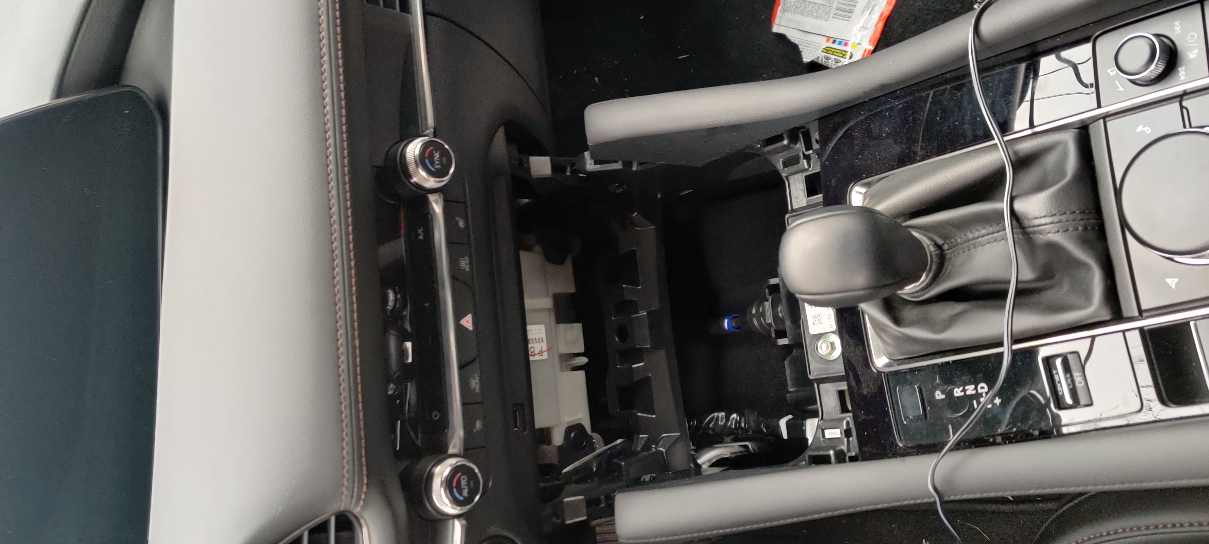
Center console with some disassembly.
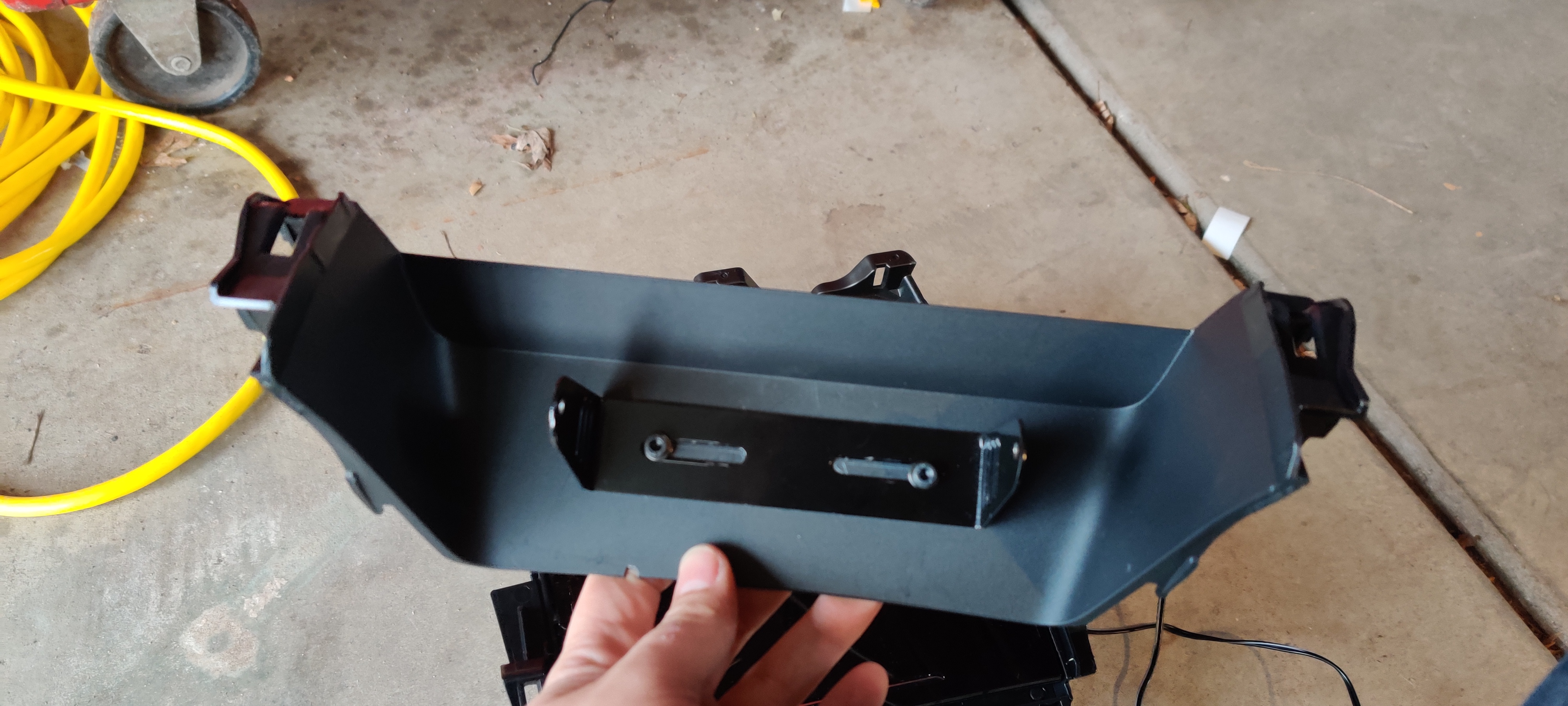
Bracket mounted on valence.
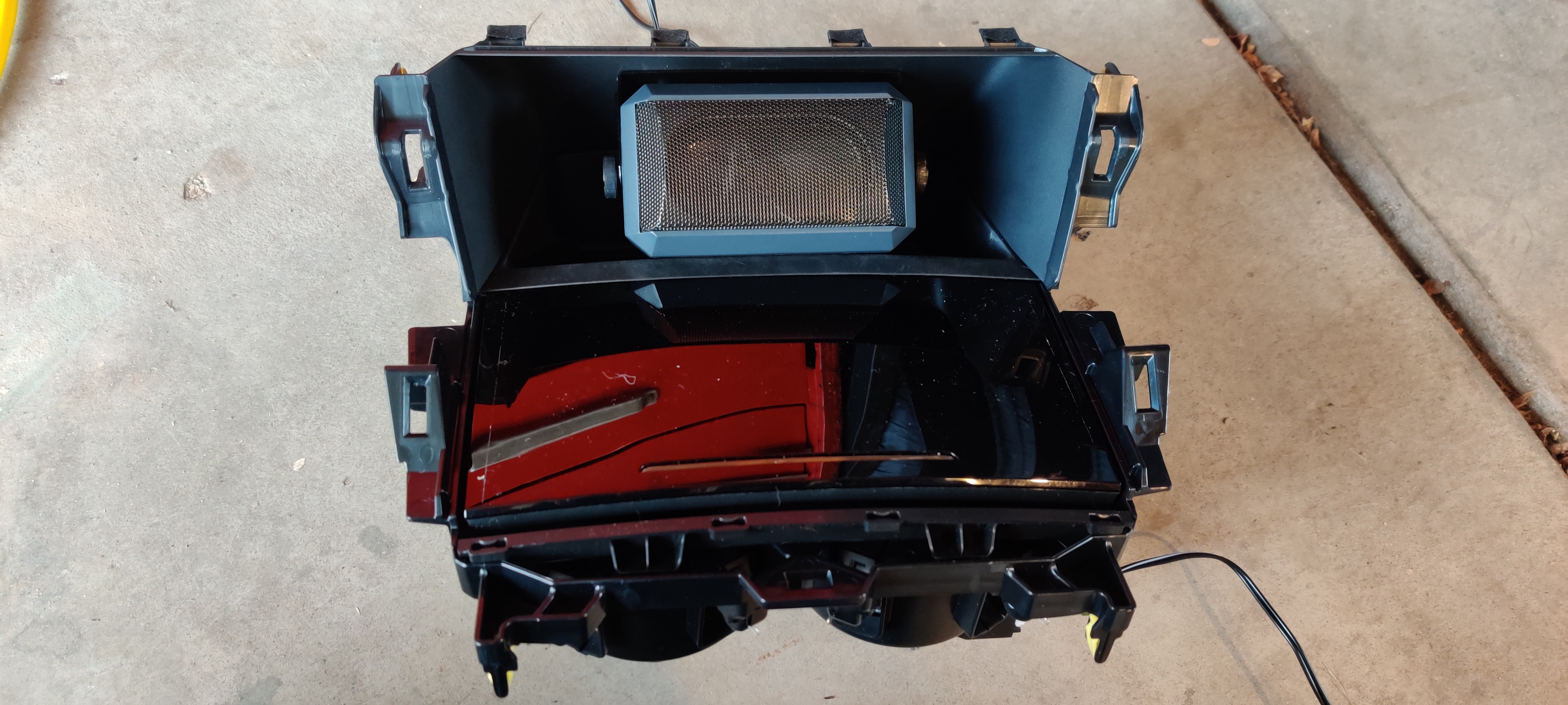
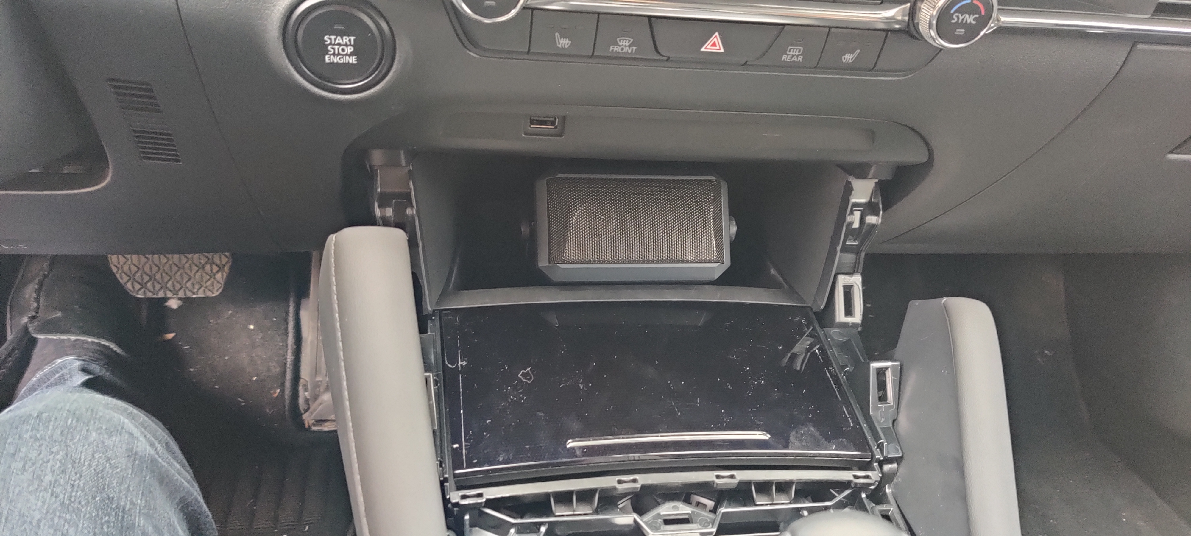
Cupholder module assembled with speaker installed.
Cupholder reinstalled, working the valence with speaker into place.
Everything back into place, now to reassemble the console.
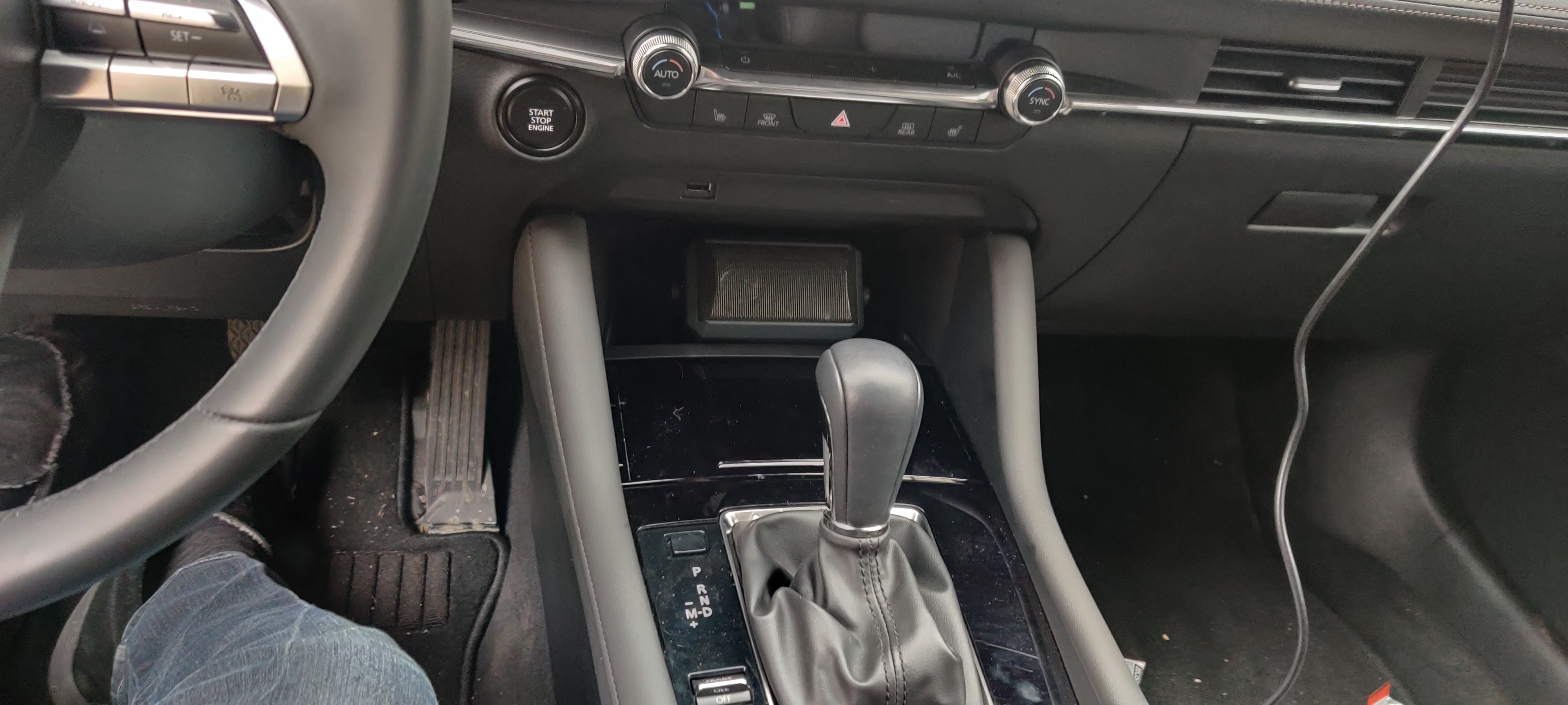
Everything complete, cupholder door closed.
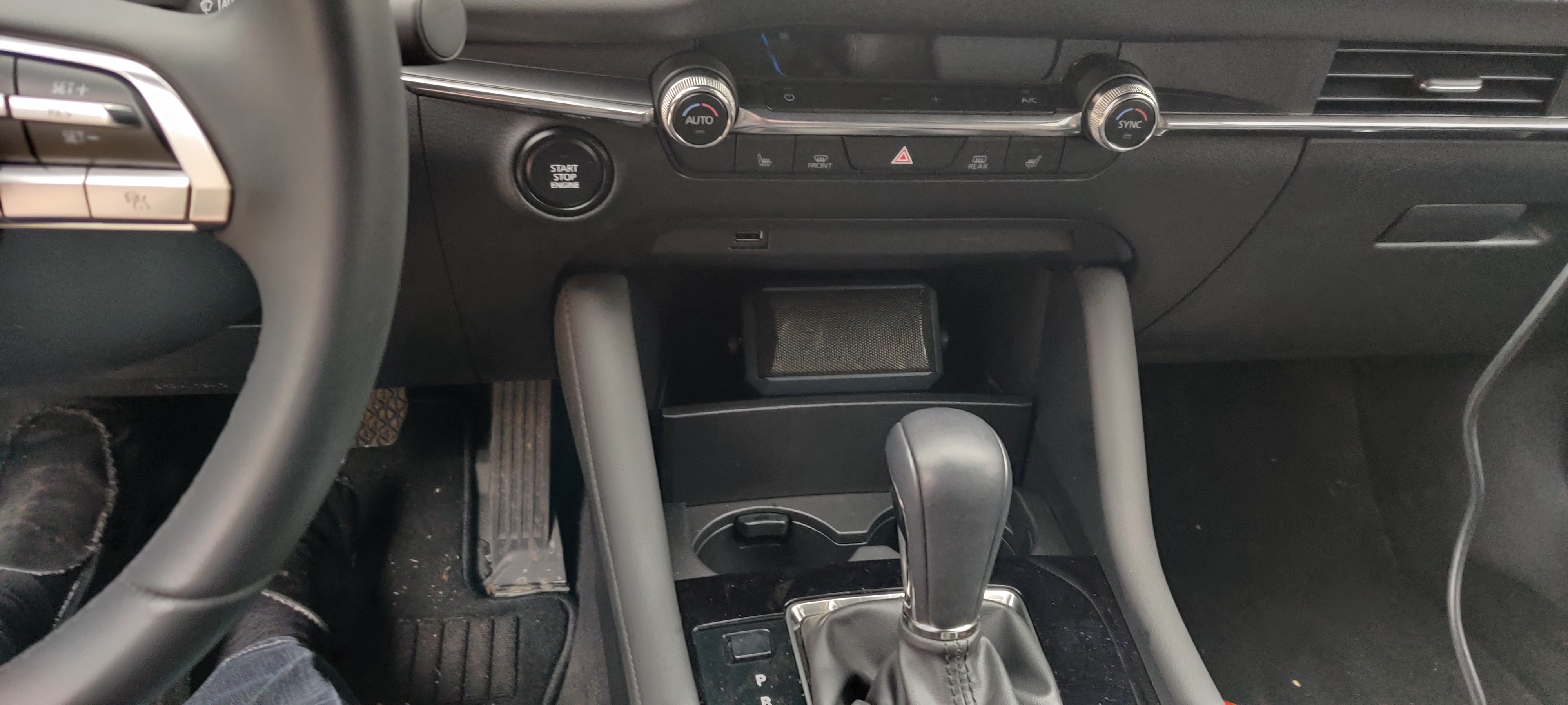
And yes, of course the door opens and there is plenty of space for drinks.
Remaining Tasks
No project is ever finished. Next up for this one:
- Pack the mounts with dielectric waterproof grease (I do not trust some of the metal-on-metal seals in the mounts and I like automatic car washes)
- Find an SWR meter and retune the HV-7A for its new situation
- Install the mixer in place of the 1-2 switch
- Install the programming cable extension and Bluetooth adapter for the FT-857D
- Install the connector caps for car washes
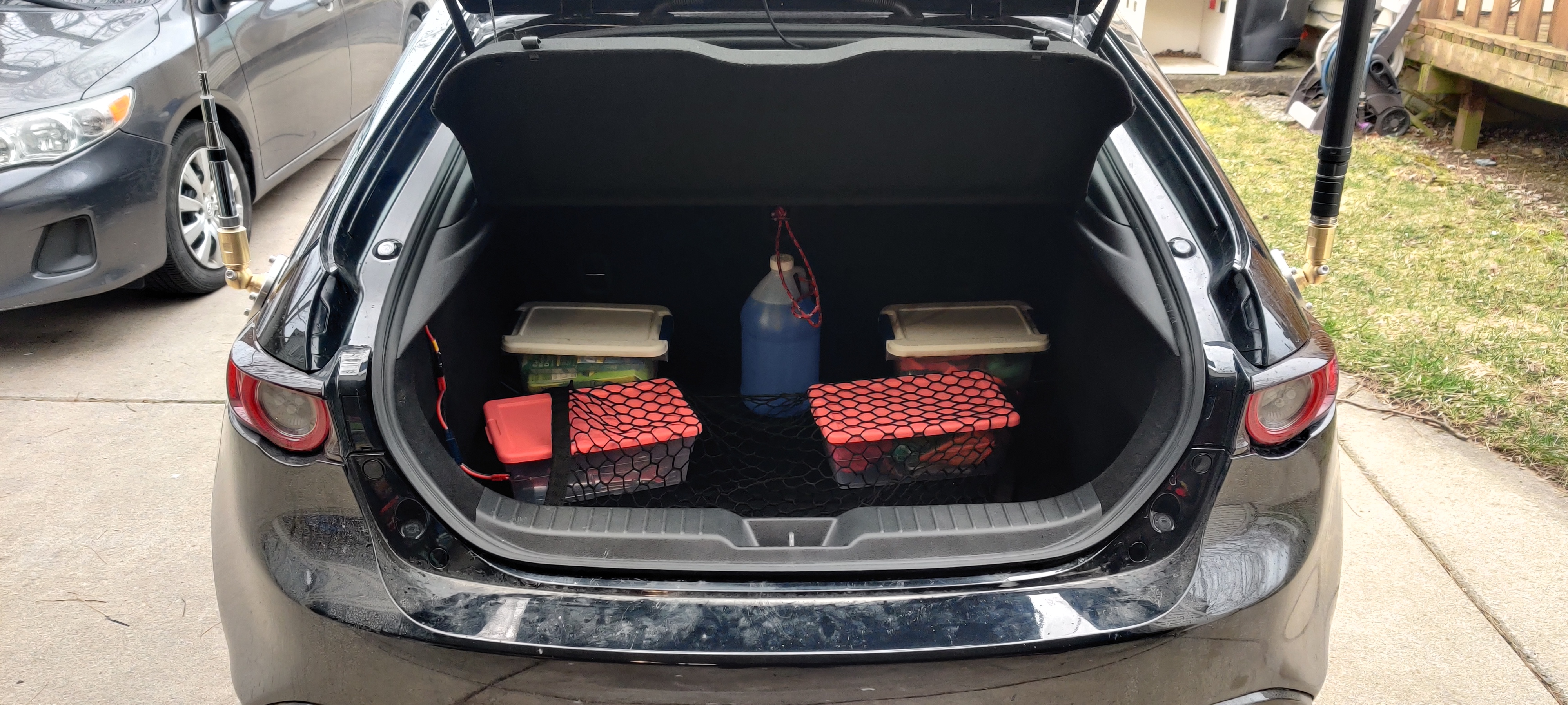
Cargo area fully buttoned up, showing both antennae.
KE8HOJ mobile, 73 and clear!